Limits to cam timing
In anything but perhaps the most simple of designs the complete camshaft profile cannot be described by a single mathematical expression. Thus, when designing an engine camshaft, the profile will consist of a number of segments described mathematically and joined together to form a continuous surface, each segment being devised to create the motion desired at the valve. Where adjacent segments meet, this mathematical relationship has to converge to produce what is known as third-order continuity, such that the follower can travel smoothly between boundaries with minimum upset. At these boundaries therefore the three orders of lift, velocity and acceleration have to align.
The primary goal of any camshaft though is to assist the opening and subsequent closing of the valves in the shortest space of time, to ensure the greatest flow of air into the engine in the time available. In direct-acting tappet designs the velocity of the valve is limited by the diameter of the rotating follower, while the acceleration is limited by the forces in the system and ultimately the strength of the spring with which to slow the valve down again as it reaches full lift.
At full lift of course the situation changes, and suddenly the issue is likely to be one of Hertzian stress just below the surface on the camshaft nose. For the return journey back to its seat, for many years the profile would have been a simple reflection of the opening phase, but of late, with the widespread availability of cam design software, the complex mathematics involved is no longer an issue. In the distant past, crunching all the data to develop the lift, velocity and accelerations (and possibly even jerk if you were keen) and getting them to match at each node, would simply have little or no time – let alone the will – to design a different closing profile. The tendency therefore was to repeat the opening flank but in reverse. Ensuring the valve landed gently back onto its seat was, however, often a problem.
But having designed the cam motion as above, the great concern now is to ensure that, with modern compact combustion chambers and large valve lift and diameters valves, the timing is optimally set to give maximum power without valve-to-piston contact. At this point I am reminded of a conversation with a championship-winning engine builder going back to the days before ‘crate’ engines. In those days, even though the series engine regulations were very restrictive, the camshaft timing relative to the crankshaft was still unregulated. Naturally engine builders do what they invariably do and, having experimented with all the normal engine ‘tweaks’, this builder resorted to altering the camshaft timing, particularly that of the intake cam. The engine already had valve-shaped cut-outs in the piston which, under the engine regulations, could not be altered, but testing had revealed that the engine performance clearly increased with advanced camshaft timing. The question was: did it go on climbing into the region where the valve might hit the piston?
Finally, and saying a short prayer as he did so, the builder advanced the cam to the point when it was just about touching the piston at top dead centre and then, with fingers crossed, ran the engine again through another power curve. The fact that the engine survived is a matter of record, and with it too the marginal increase in top-end performance such a tweak produced. Unfortunately this was at the expense of a slight drop in maximum torque at a lower speed and so – both to sleep at night and preserve his customer’s championship lead at the time – the decision was taken to retard the cam back to its former position.
The interesting thing was that, after stripping the engine, a clear mark remained on the top of the piston where the valve had just about been in contact with it – not quite enough to cause mayhem but in reality close enough to remove the carbon from it, leaving a patch of almost clear aluminium.
Now that’s what I call optimal cam timing!
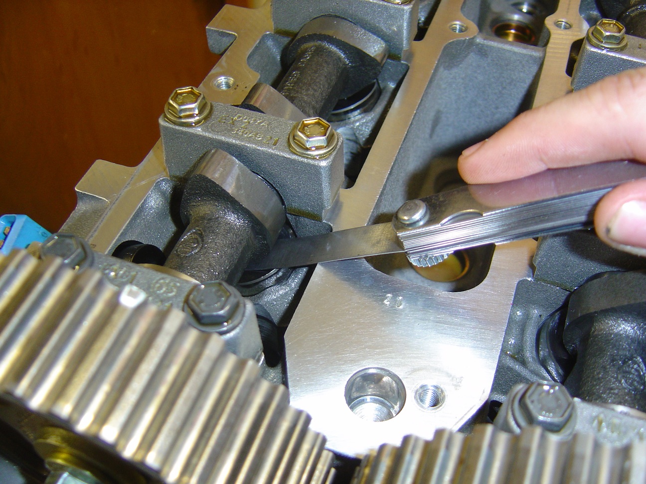 Fig. 1 - Setting valve lash can sometimes be critical
Written by John Coxon