The emulsion tube
When it comes to carburettors there are essentially two types each working on differing principles –the constant depression device or that of the fixed venturi, sometimes referred to as fixed jet. Because of their simplicity and ease of setting up, many vehicles in the past have been fitted with constant depression-type units, but where ultimate performance is required and although difficult to ‘tune’ – or as we now say, calibrate precisely – the choice is almost always that of the fixed jet or venturi principle.
The fixed-jet carburettor works by pulling fuel from a reservoir in response to a pressure signal from the venturi in the engine intake air. The depression thus created causes fuel to flow from the fuel reservoir in the carburettor while at the same time encouraging a small flow of air at atmospheric pressure to mix with the fuel. The fuel is metered through the main jet while the air is controlled through what is generally called the ‘air correction jet’. Somewhere in between, the fuel and air are intermixed to form an emulsion – a fine dispersant of the air inside the fuel. This assists the atomisation of the fuel as it eventually enters the engine airstream.
At times of low fuel demand, the air drawn in is very small and the fuel flow regulated by the main fuel jet will contain little in the way of an emulsion. With the throttle only slightly open, drops of liquid fuel will land on the throttle plate and atomise thereafter into the air. However, with increasing engine speed or load, as the fuel demand increases then the restriction of the main jet causes an increased depression in the air correction circuit, and this air passing through the emulsion tube effectively leans off the mixture: the higher the engine speed or load, the greater this air correction effect. Metering the fuel and the air is one thing, but mixing it and presenting it in a form so it readily mixes with the intake air is quite another. This is the function of the emulsion tube.
The essential points to remember are that the fuel passes around the outside of the emulsion tube at its base while air, coming from the top, comes down the inside of the tube and is extracted through a series of drilled holes of varying sizes and heights to mix with the fuel on the outside. When the engine is stationary, the fuel level will be the same as that in the float chamber, and will come to a level within the emulsion tube. As soon as fuel is demanded, the fuel level will drop in the chamber, uncovering more holes that will allow more air to mix, thus leaning the mixture.
As well as altering the size and height of these holes, it is also possible to alter the diameter and thickness of the emulsion tube in its cavity within the body of the carburettor. This acts as a restriction to the flow of fuel which, when all fashioned together, can tailor the flow of fuel more or less precisely to that required by the engine throughout its operating map. Under wide-open throttle acceleration the emulsion tube plays little part since the overriding effect is that of the main and air correction jet. At part-throttle however, when the quality of the fuel atomisation arguably has to be significantly better, the emulsion tube can be considered more critical. Understanding this and being able to apply it in practice is therefore one of the dying ‘black arts’.
Setting up a fixed-jet carburettor may be a long and often confusing business, but when the vehicle starts and drives smoothly and progressively, the satisfaction is immeasurable.
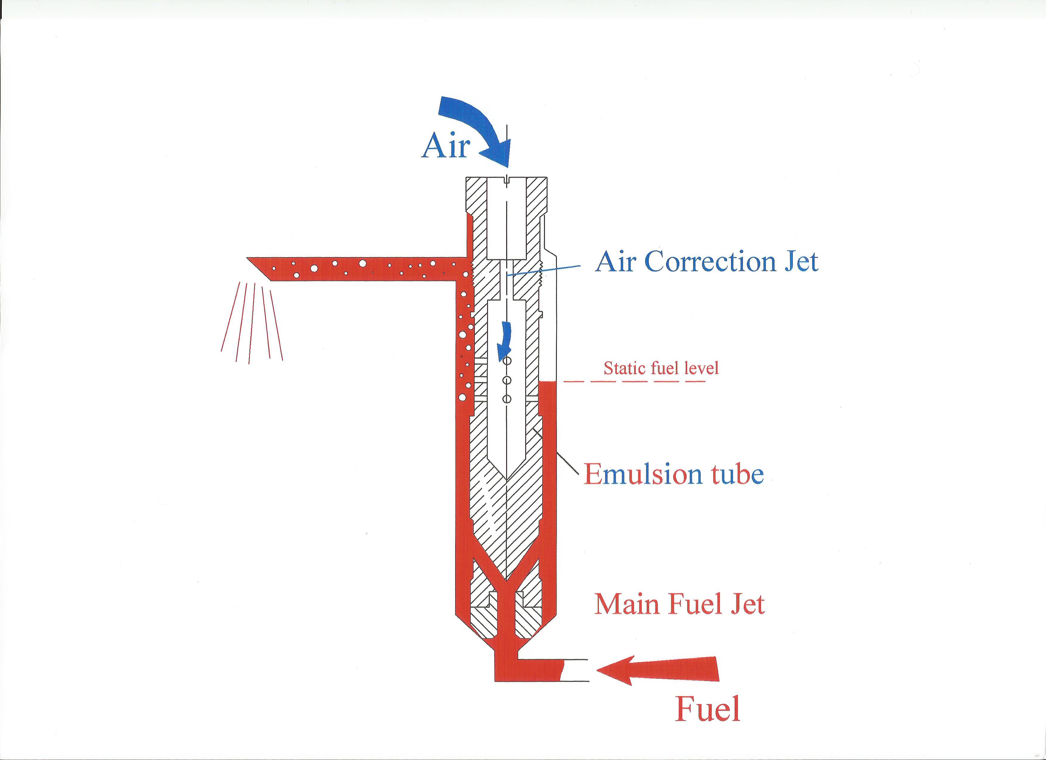 Fig. 1 - Fuel enters through the main jet at the bottom and flows out of the large holes just above the base. Meanwhile, air comes in through the air correction jet at the top, coming out into the fuel through the small holes midway down
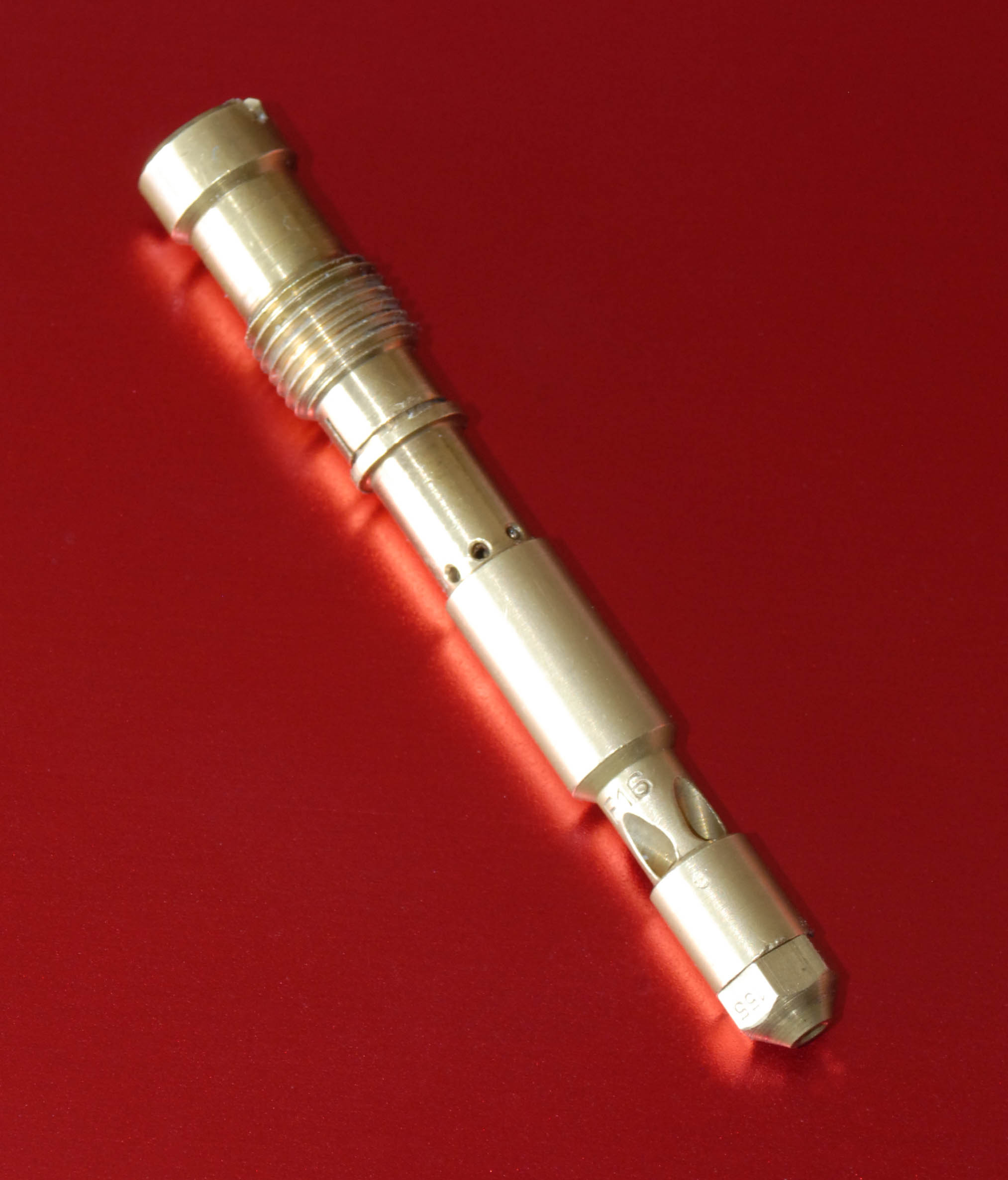 Fig. 2 - Emulsion tube from a fixed-jet Weber DCOE carburettor
Written by John Coxon