Weighty matters
 In these financially straitened times, the fuel consumption of engines has taken on a new level of importance - not, I hasten to add, to minimise the production of carbon dioxide and its environmental impact on the world but, within motorsport, the simple realisation that every unnecessary litre of fuel weighing 0.75 kg, is 0.75 kg too much. Irrespective of the current financial climate therefore, minimising fuel usage seems to make so much more sense. That being the case, in any engine test cell, the fuel flow meter is now a thing of worth.
At this point it is perhaps worth pointing out that while there are any number of methods of determining fluid flow, only those that don't appreciably change the pressure in the fluid are suitable for measuring gasoline. Any method (such as a simple orifice plate) that can introduce a vapour state by reducing the pressure in the fluid - even if only instantaneously - surely has to be avoided.
One of the easiest ways to measure volume flow, and that used successfully by myself for many years, is what I refer to as the 'pipette' system. Consisting of a number of different-size vessels or bulbs shaped like a pipette - 25 ml, 50 ml and sometimes even 100 ml depending on the fuel flow rate and accuracy required - the time was measured for the level of the fuel to flow down from a mark at the top of the pipette through the glass vessel to a mark in the lower pipe. With the time measured using a handheld stopwatch, in the days when engineers would routinely work from within the cell, this was a cheap and surprisingly accurate method of measuring volumetric fuel flow.
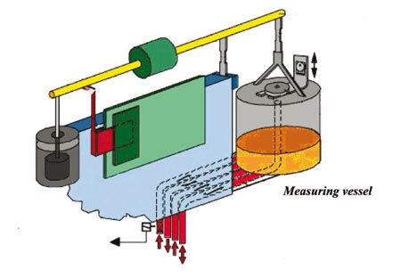
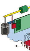
A little more sophisticated but relying on more or less the same principle is the electronically controlled fuel balance. Triggered by pressure or position sensors in a balance system, the time taken for a defined amount of fuel used is measured and the output of average fuel consumption then fed directly into a data acquisition system. Increasingly however, as engineers need to know more about the actual rate of fuel usage, a totally different concept is used - that of the Coriolis meter.
To anyone not entirely familiar with it the Coriolis principle states, "A mass revolving in a circle, which is then also subject to rotation in a plane at right angles to the first plane of rotation, will experience a force in the plane at right angles to the other two planes". It sounds a bit convoluted but the effect can be demonstrated by holding a spinning bicycle wheel between two hands. If you subsequently try to turn it parallel to the ground, it will twist in an unexpected direction.
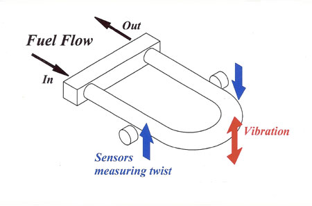
Applying this to a quantity of fuel flowing through a pipe, if the fuel flowing around a loop is subject to a vibration in a plane at right angles to it, a force will be generated much like the force on our bicycle wheel. And as the fuel flow rate increases, this Coriolis force will also increase in proportion. The effect can also be produced in a straight tube excited by some form of electromagnet in the centre. Furthermore, while single-tube devices can measure mass flow, if the flow is split, twin-tube devices excited in an equal and opposite direction can not only measure mass fuel flow but density as well, and will have the additional advantage of being less susceptible to general vibration within the test cell.
Best of all, however, with typical turndown ratios of 100:1 and claimed accuracies of ± 0.1%, Coriolis fuel flow meters are a welcome enhancement to any test cell.
Fig. 1 - The fuel balance
Fig. 2 - The Coriolis meter
Written by John Coxon
4102