Location of connecting rod caps, part 1
 In an article published in 2009, I looked at some of the design features of the joint face of a split con rod. One important requirement is that the two parts of the con rod - the 'blade' of the rod and its cap - must be positively and reliably located with respect to each other.
It is important that these location features are machined into the rod before the big-end bore is finished to size. This guarantees that when the rod is assembled and the bolts pre-loaded to their design load, the big-end bore should take the same form as it did immediately after final machining. If the two parts of the rod are not positively located, the misalignment could cause serious problems, with bearing clearances and rod-end float likely to be affected.
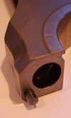
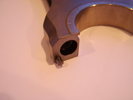
There are several methods of achieving this location, one of the most common of which is the use of location pins or dowels, one on each side of the rod. Given the availability, quality and price of loose rolling elements from needle roller bearings, these parts are often used as location pins for con rods.
Another common method is to use ring dowels. As the name suggests, these are hollow dowels and are designed to fit concentrically with the big-end bolts. They are used in pairs, with one concentric with each bolt, and are generally a tight fit in either the blade or the cap, and a light push-fit in the opposite half. Practical advantages with this method are that the machining is relatively inexpensive and the tooling is quite sturdy.
These two methods are quite similar in approach, using two cylindrical components to locate the two rod halves. The ring dowel has a larger cross-sectional area compared to the smaller pins and can therefore add a little to the 'shear stiffness' of the joint face, thereby better maintaining the location of the two halves during operation.
However, one disadvantage is that the dowel necessarily moves the bolt axes further away from the big-end bore than could be achieved using dowel pins. The result is that the maximum stress in the bolt is increased in service due to increased bending loads in the bolt shank.
The minimum distance that the ring dowel causes the bolt axis to move, relative to a rod whose parts are located with pins, is equal to the wall thickness of the dowel plus the radial clearance between the bolt and the inner wall of the dowel. We can see that, in order to minimise the increased bending stress in the bolt, there is an incentive to use dowels with little radial clearance to the bolt and as thin a wall as is possible while maintaining accuracy of location.
One method that would keep the bolt axes close to the big-end axis without having to use pins or dowels would be to use a location diameter on the bolt which is a close sliding fit in both halves of the rod. However, this method is rarely used.
Fig. 1 - This con rod uses one pin on each side of the rod to maintain location between rod and cap (Courtesy of Vitesse Engineering Services)
Written by Wayne Ward
6689