A breath of fresh air
The internal combustion engine is, I suppose, a bit like the human body, in that it takes in oxygen at one end, burns it to create energy and then expels the waste gases to the atmosphere. And also like the human body, give it too little oxygen and its performance suffers; likewise too much. But just like the baby bear in the tale of the three bears, somewhere between too salty or too sweet, rich or lean, the mixture is just about right.
In calibrating the engine, engineers can of course plan it so that a precise amount of fuel is injected according to the prevailing conditions in the cylinder at any time, but to ensure that the engine is running at the optimum condition requires some kind of oxygen or lambda sensor.
Developed in the early days of electronic fuel management, lambda sensors are truly only required where fuelling precision is of great importance. Gasoline engines for instance will run quite happily at air-to-fuel ratios anywhere from 10:1 right up to 20:1-plus, but to get best performance then 13:1, depending on the engine, is the right amount, while the best fuel efficiency is obtained nearer 16:1. Mounted in the correct place along the exhaust pipe – neither too far down (where it won’t heat up quickly or become fouled) nor too close (where it might overheat) – the lambda sensor, as part of a feedback loop, is essential for accurate fuelling.
Early sensors were designed to run with three-way catalysts, and as such could only control to stoichiometry, where lambda = 1.0. Operating according to galvanic principles, porous platinum coatings are used to form a sandwich with a solid zirconium dioxide electrolyte separating the exhaust gas from the atmosphere. If the exhaust gas is denuded of oxygen – that is, the mixture is rich – then the cell’s output will be around 0.2 V. As soon as oxygen enters the exhaust and the mixture is lean, this changes more or less instantaneously to 0.8 V. Therefore, in order to pinpoint the precise position of stoichiometry, the control system has to effectively flip-flop between rich and lean settings where the average voltage output will be of the order of 0.5 V.
Referred to as a ‘narrowband’ sensor for obvious reasons, these are no good for competition engines or those that need to work at settings richer or leaner than lambda = 1.0. For these, so-called wideband or broadband sensors have been developed. Similar in a way to the narrowband sensor, wideband sensors incorporate an additional cell where the current output directly indicates the oxygen content of the exhaust gas. Eliminating the flip-flop control of the narrowband sensor, the output is therefore a continuous curve more suitable to modern fuelling control strategies, enabling a much higher level of accuracy when controlling outside of the lambda = 1.0 range. Indeed, special motorsport sensors have evolved that are more capable for the rich (lambda less than 1.0) end of race engine control strategies, offering increased resilience over roadcar units designed more suitably for the lambda = 1.0 and lambda > 1.0 regions.
And what is also quite useful, when fitted with some kind of digital readout, wideband lambda sensors can be used to ‘tune’ engines fitted with good old carburettors. Now that really is something to be thankful for.
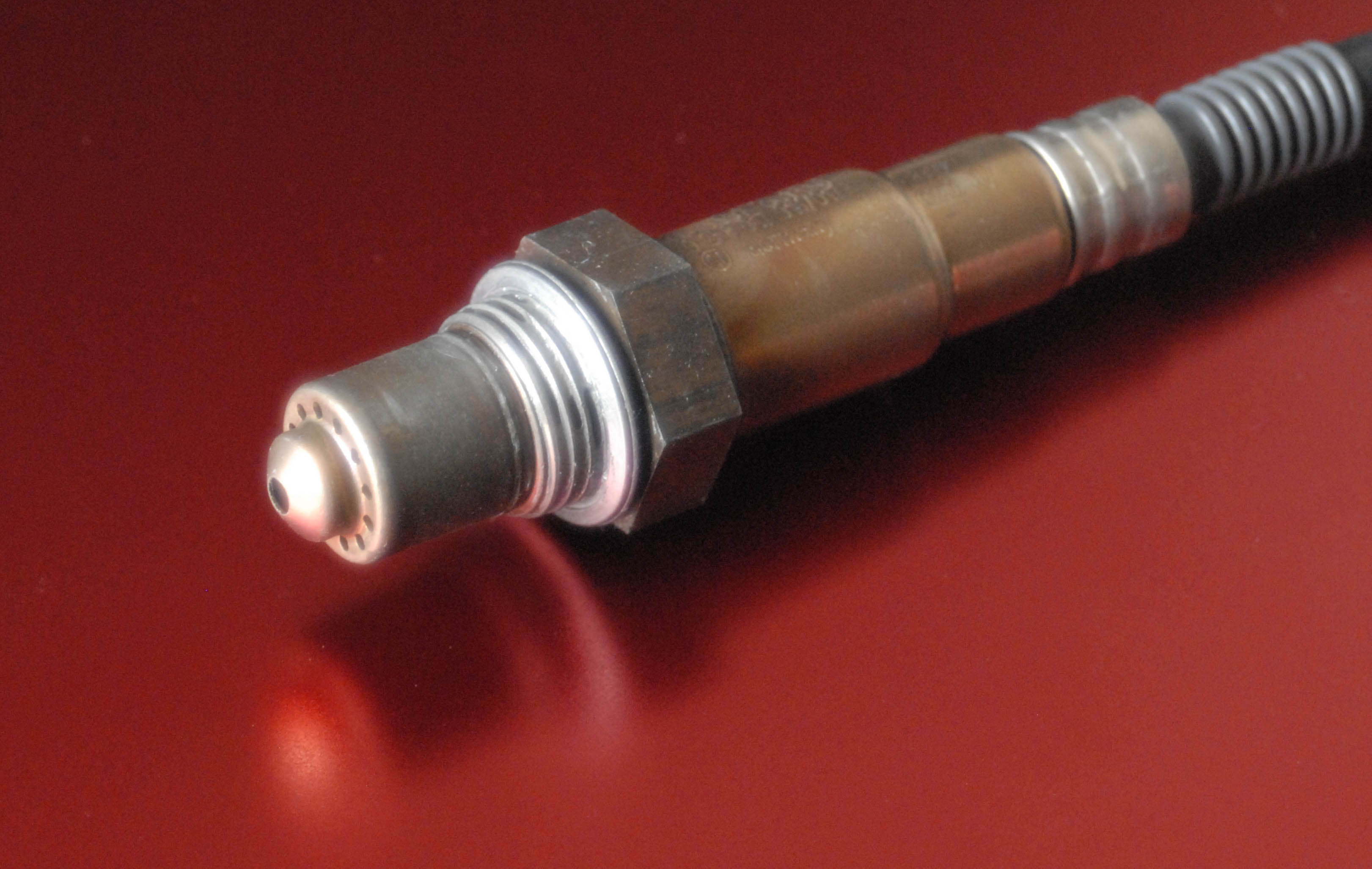 Fig. 1 - Lambda sensor
Written by John Coxon
3263