A most unusual engine
 An engineer should not only have solid grounding in the fundamentals of his discipline but an interest in history too. A thorough understanding of the principles involved in product design is, I would have thought, an absolute necessity but an appreciation of all that has gone before is as equally valuable. So when other people are perhaps relaxing or enjoying the fruits of their labour I often prefer to saunter around some of the smaller transport museums in this land. On one occasion hidden behind a glass case I came across an aluminium casting labelled 'Part of a prototype engine' and realised that, very many years ago now, I had actually worked on that programme and that the part they were exhibited, although not recognisable as such, was indeed one half of the cylinder block.
A considerable amount of any design and cost in any reciprocation engine goes into the cylinder block/crankcase assembly. Often split at the bearing line horizontally forming the face to which the sump is attached, as it was then, or more commonly now the bearing ladder, the cylinder block is a complex relatively heavy casting using many internal cores. Along with complexity comes the difficulty, not only in casting but also machining such that any traditional cylinder block is a considerable investment. This part of a prototype engine was therefore an attempt to move away from this complex and expensive approach having the main bearing split not horizontal and parallel to the cylinder head face as is normal, but vertical, running up through the cylinder bores and perpendicular to the cylinder head face. Such a concept, nicknamed quite appropriately 'the vertical split', greatly simplified the cylinder block casting although did introduce one or two other development issues.
In addition to the much simpler casting requiring no internal cores, for the first time the sump could be included as well. Using two identical crankcase halves which would be clamped around the pre-assembled cylinder liners/pistons and crankshaft, the engine was fastened together using 10 (it was a four cylinder) transverse bolts, one above and below each of the five main bearings. In between the cylinders the castings were bolted together using lots of tiny bolts while along the base of the sump the castings were clamped using long thin plates and bolts traversing the whole width of the unit. The two halves were sealed using anaerobic sealants, the first recorded use in engines to my knowledge, and the lower cylinder liner seal was injected after assembly using a 2 part specially designed sealant into holes leading to the machined grooves.
After a few development issues, some minor, others quite major, the engine ran for well over 300 very tough hours on the dyno. When stripped for inspection, despite some concern that the main bearing split line occurred close to the maximum main bearing pressure zone, all the bearings, bores and piston rings showed no obvious signs of distress. More importantly, we had proved that there is more than one way to cast a cylinder block!
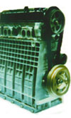
Fig. 1 - The vertical split engine.
Written by John Coxon
3174