Active dyno test cells
Advanced active engine dynamometers are invariably housed in test cells, where the test environment can be closely controlled. This month I want to look at the design and engineering requirements of these cells, specifically the installation and types of ancillary systems including, but not limited to, coolant and environmental systems.
Engine testing is essentially a scientific experiment and, as such, as many factors as possible need to be tightly controlled to ensure reliable and repeatable results. The biggest factor is the environment within the test cell.
This may seem initially like a simple matter of installing a basic HVAC system to ensure the temperature and humidity remains stable, but a common mistake made when building a test cell is the level of heat rejection from even a small-output I/C engine. For example, an engine delivering 100 flywheel horsepower to the absorber (74 kW per hour) radiates up to 32 kW per hour into the cell from its exhaust, cooling radiator and block surfaces.
Even at idle, when zero crankshaft horsepower is available, significant heat energy must be dealt with, as the engine is still burning fuel in overcoming its internal friction. As a conservative estimate, a test cell with the exhaust routed outside the cell will need about 2000 cfm of air-moving capability per 100 bhp of engine output.
In a well-designed cell the oil and water coolers will also be located outside the cell, which will reduce the level of radiated heat, but the volume of cooling air required will still be substantial. Other equipment such as double-walled and insulated exhaust systems can also be used to reduce the level of radiated heat. Many manufacturers of test systems will also be able to supply suitable HVAC equipment, with the specification based on the specific requirements of a particular dynamometer.
The extraction of exhaust gases also needs to be considered. Some basic cells will use a hood that's very similar in concept to those found on a domestic oven (but obviously much larger) and that draws air and exhaust fumes out of the test cell. While simple, this system is not ideal and cannot ensure that all fumes are extracted; a far better solution is to use a sealed extraction system. The use of a hood also prevents the use of jibs or cranes to move engines and equipment into the test cell.
Carbon monoxide inside the test cell is another important consideration. Inadequate airflow, improperly sealed construction or positive pressure inside the test cell will result in CO leaks. Since it is odourless, colourless and deadly at low PPM levels there should be a small amount of negative pressure (0.25 in of water) in the cell at all times during testing, to prevent CO from being pushed out into other areas of the facility.
CO present in the combustion air will also displace oxygen and degrade the power output of the engine under test. Exhaust extraction systems that connect directly to the header pipes can be used to extract exhaust gases; however, the system introduces negative pressure into the exhaust side of the engine and ultimately affects performance, air-fuel ratio tuning and timing aspects of the engine while it's on the dynamometer.
One final factor that needs to be considered is the control of these ancillary systems. Having four or five different control panels dotted in and around the test cell is not an ideal solution. It makes more sense for all the HVAC and other services to be handled from the dyno control room where they can be controlled and monitored by the dyno operator without distracting from the primary task of running the engine test.
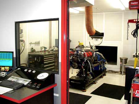
Fig. 1 - Careful planning of the layout for a test cell will make testing operations easier to control for the dyno operator."
Written by Lawrence Butcher
5186