Advances in optimisation software
Computer-aided engineering packages are the primary tools used by Formula One engineers to design, develop and manufacture their racecars. The use of finite element analysis (FEA) and computational fluid dynamics (CFD) simulation has intensified over the past 20 years as computing power has continued to increase, enabling more complex models to be solved in the shortest timescales.
The increasing complexity of the modern racecar, from both structural and aerodynamic perspectives, has led to a reliance on simulation software to evaluate and optimise designs. Materials and aerodynamic behaviour can no longer always be predicted confidently without these tools, and they offer engineers a fuller understanding of the physics governing performance.
The recent FIA restrictions on wind tunnel and track testing have further increased the dependence on simulation software, particularly CFD codes, but their use is also now limited by the technical regulations. The consequence is that Formula One engineers need optimisation tools that work faster and smarter to maximise performance in the shortest timescales.
The traditional approach for optimisation using simulation software is to evaluate the design, make geometric modifications based on the results and engineering experience, and then re-run the simulation. This design loop is repeated until the required performance is obtained, and it can be a protracted process, with the need to re-mesh and solve the models for each geometric iteration.
It is also not guaranteed that the changes implemented will produce the desired or anticipated results, with the stress distributions and flow regimes calculated not necessarily being intuitive. This can lead the design in the wrong direction, wasting time and resources on pursuing the ‘wrong’ solution. In addition, to ensure a robust solution is reached, there are many potential variables to consider, which increases the simulation overhead.
There are however some software technologies being developed that may provide an answer to these challenges and accelerate the path to an optimised design. For example, topology optimisation software can be used with FEA solvers to generate conceptual designs for lighter and stiffer structures based on ‘minimum metal’ solutions. Existing designs can be improved using shape-optimising tools that automatically modify a component’s surface geometry to minimise stress and strain, or a combination of parameters, to deliver more reliable and efficient parts.
Similarly, adjoint solver technology can be combined with CFD codes to optimise aerodynamic performance. In standard CFD methodology, a number of inputs such as the properties of air, ground roughness and angle of attack must be described to define the problem. These inputs are then used to calculate the flow information desired by the engineers – for example, vortex shedding, exhaust gas mixing, brake cooling and so on. Adjoint technology reverses this approach though, and effectively asks how the input variables can be altered to effect a particular change in the output results. For a racecar, geometry represents one of these input parameters, so by exploring how the shape of a front wing, say, must be altered to increase downforce, the adjoint solver – coupled with a tool to automatically ‘morph’ the surface geometry – can deliver an optimised solution after it has evaluated multiple geometric options.
Fig. 1 shows the improved downforce-to-drag ratio achieved using adjoint solver technology to modify the endplate geometry of a simplified Formula One front wing in a straight-ahead position. In reality, on track the car experiences a multitude of conditions, from ride height and speed changes to varying cornering rates, so to give a robust and optimised solution all these permutations need to be considered by the solver. If it is assumed that during a lap the car’s geometry is fixed then the circuit’s characteristics can be condensed into a probability density function (PDF) that is then used as an input into the adjoint solver.
Fig. 2 shows a graphical representation of all steering angles and velocities experienced by the car around a lap of Monza, and characterises the track’s unique identity (for these parameters). This PDF is then used to sample design points for the adjoint solver where steering angle and free-stream velocity are adjusted for each point. A mean value penalty (MVP) distribution is selected such that the downforce-to-drag ratio is significantly shifted for the entire range of defined steering angles and velocities to provide an improved performance over the entire lap, as shown in Fig. 3.
The geometry is automatically morphed in the software, and the blue wing in Fig. 4 shows the optimised design that corresponds to the density function shown in blue in Fig. 3. This wing is optimised for a particular track, not a single condition, and the changes implemented by the adjoint solver would have been difficult to predict in advance.
There are of course some challenges to overcome before topology optimisation and adjoint solvers become mainstream tools in an engineer’s development toolbox. For example, there can be issues with the optimised geometry generated, resulting in designs that are difficult or impractical to manufacture, although these are already being addressed, with parameters such as production costs being used to influence the optimisation process. There is also the challenge of exporting the optimised geometry back into the CAD packages so that it can be engineered for manufacture.
Questions may be asked regarding whether these tools are eroding the skills of the engineer, but ultimately it will be the engineer’s knowledge as to how to define the input parameters and boundary conditions, and their ability to interpret and evaluate the results, which will make these tools valuable.
These optimisation technologies are starting to provide real opportunities for accelerating the development and optimisation of designs, and look set to provide a significant competitive advantage to the Formula One teams that adopt them.
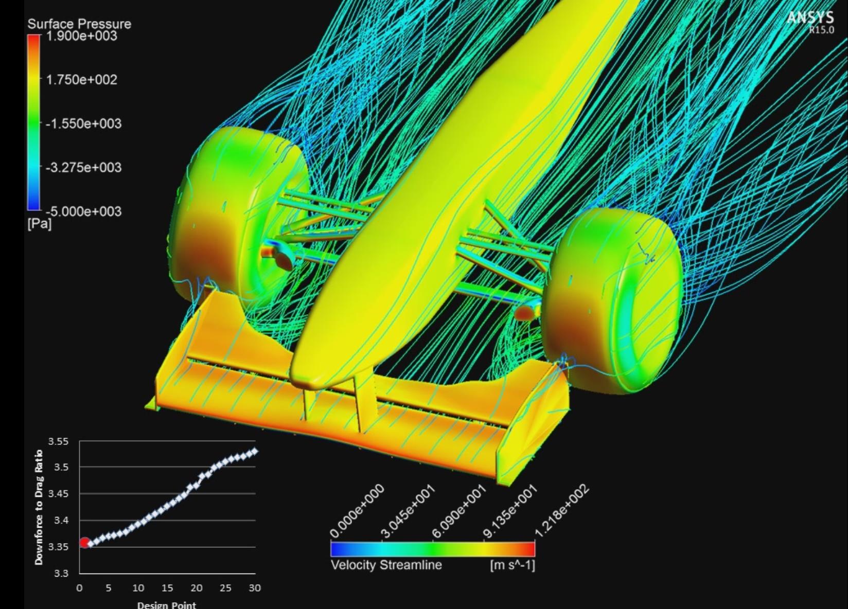 Fig. 1 - Improvements in downforce-to-drag ratio using an adjoint CFD solver on a generic Formula One front-end geometry
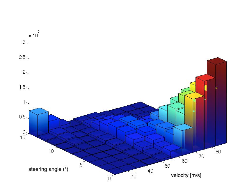 Fig. 2 - Derived density function for the Monza track
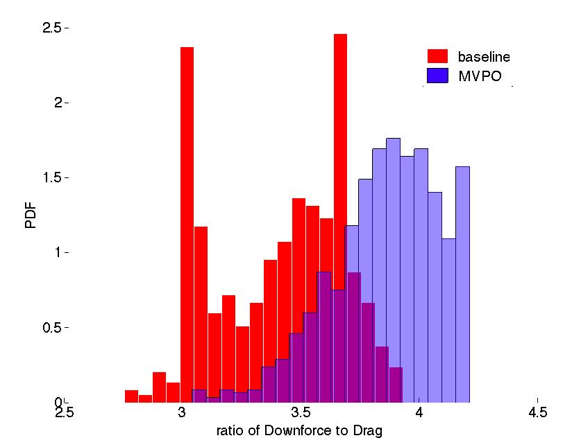 Fig. 3 - Downforce-to-drag density functions for the baseline geometry (red) and optimisation wing geometries (blue)
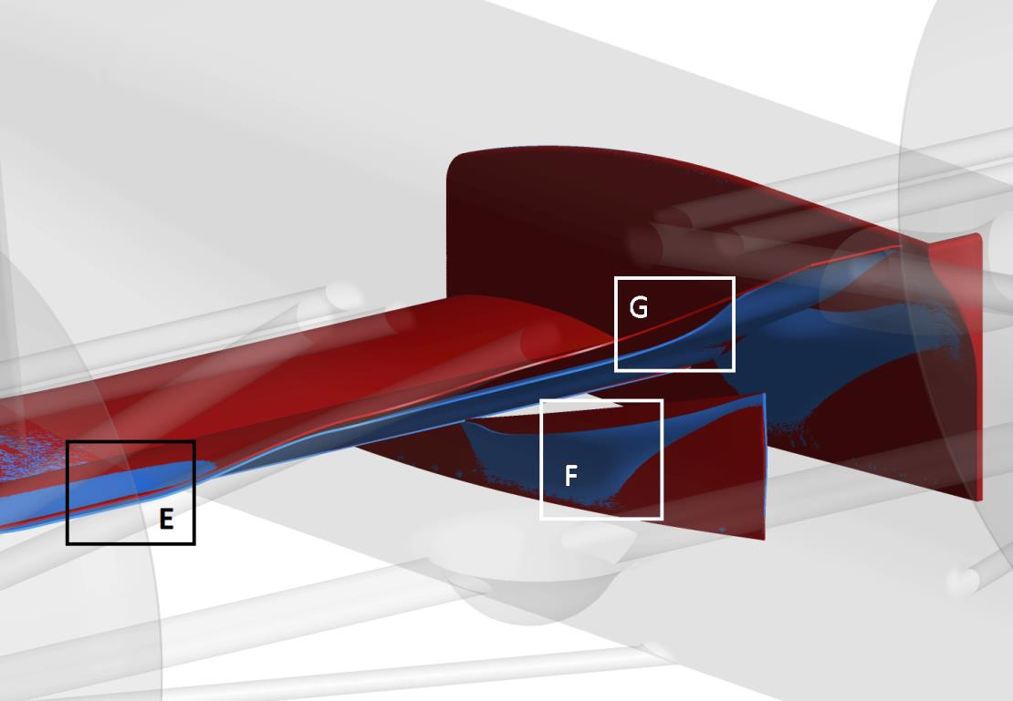 Fig. 4 - Blue wing showing the optimised geometry against the baseline design (in red) corresponding to the density function in blue in Fig. 3
(All images courtesy of Ansys UK)
Written by Dan Fleetcroft
5028