Aerodynamic counterweights
 In the search for increased performance, the common direction of engine development has been to increase engine speed incrementally. While this trend is somewhat on the wane - owing to various regulations such as absolute rpm limits as in Formula One, fuel capacity/flow limits or the NASCAR 'gear rule' - high engine speeds are a good way to raise performance, providing that efficiency can be maintained.
With increased engine speeds comes increased component surface speeds, so crankshaft counterweight speeds are significant. Little wonder then that a common practice on bespoke racecar crankshafts is to 'knife-edge' the leading and trailing edges of the counterweights. However, this strategy is often not as effective as many people might imagine. Because of viscous effects, the air-oil mixture in the crankcase also travels around at a significant speed, and the frictional drag on a body is related to the surface speed relative to the atmosphere through which it is travelling.
Often the more significant effect is that of oil shear between the outer walls of the crank counterweights and the inside walls of the crankcase cavities. Even a local small gap can have a significant effect.
The strategy of keeping the smallest possible amount of oil in circulation in the crankcase also has great value, as it means that viscous drag losses caused by the crankshaft sweeping through the air-oil mist are kept to a minimum, and there is less oil on the crankcase walls that might be subjected to shearing.
It is common to see crankshafts that have the same detail on the leading and trailing edges of the counterweight. In these days of fully 3D-machined counterweights, should we not expect to see the leading and trailing edges dealt with somewhat differently? We know in which direction the crankshaft will rotate in an engine, so we can identify leading and trailing edges with ease. Look at the wings on a racecar or aircraft, blades for gas-turbine engines or helicopter rotor blades. Despite widely differing designs, what they have in common is a relatively blunt leading edge and a relatively narrow 'sharp' trailing edge. The trailing edge ensures that the flow from both sides of these 'wings' is merged without significant separation of flow and recirculation in the wake of the wing. Separation is not such a problem at the leading edge of the wing, with pressure gradients helping to keep flow attached.
If we are to consider aerodynamic counterweights, ought we not also consider something more highly engineered than the 'zero-lift' devices we often see? The possibility to design a counterweight to pull oil off the crankcase walls and into the high-speed flow outside the boundary layer may have benefits in lowering shear losses and increasing scavenging.
Engine designer the late Hiro Kaneda remarked that while people look to the cylinder head for performance, the bottom end of the engine is a 'treasure chest' in which improvements in performance can be found. Certainly the mitigation of friction in the crankcase can yield significant gains (depending on how bad the situation is before development work is done). As this continues, the 'treasure' may become more sparse and harder to find. Clever thinking with counterweight design might be one way to reduce friction further.
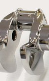
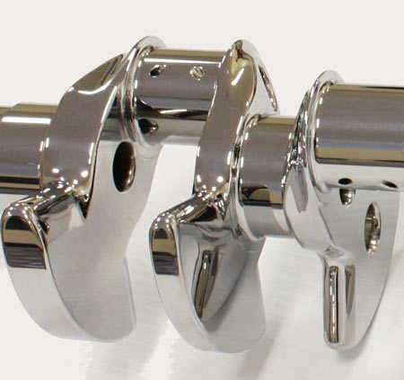
Fig. 1 - A crankshaft with carefully machined leading and trailing edges on the counterweights
Written by Wayne Ward
5010