Any hose will do?
 Oil flow within an engine is something that is given great consideration during the design stage, be it by a manufacturer of a commercial unit or a bespoke race engine. However, ancillaries such as oil coolers and dry-sump systems are sometimes not subject to the same level of scrutiny. This can often be the case when the engine is being fitted to a car without the involvement of the engine constructor.
Obviously correct sizing of the 'plumbing' is important - there is little point in having 11/16 in pipes if the oil inlets are only 3/8 in, for example. But what is of greater importance is the effect the lines and fittings can have on system pressure and, more important, the likelihood of cavitation in the oil pump.
Cavitation is a subject in its own right, but in essence turbulent flow, or a reduction in NPSH (net positive suction head) at the inlet to the oil pump can cause considerable damage and wear to the pump components. The most common cause of cavitation in a pump is the presence of tight bends close to the pump inlet. A bend causes pressure losses due to both friction and a change in momentum.
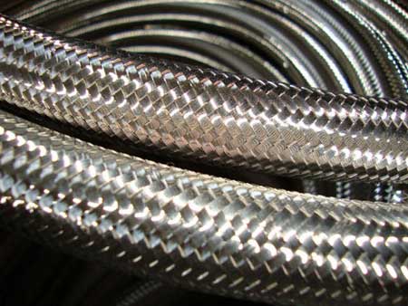
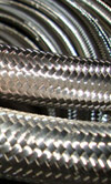
Fig. 1
These losses are dictated by the bend angle, the curvature ratio and the Reynolds number (Re) of the pipe. The Reynolds number is fairly easy to deduce, although some generalisations may need to be made. It is important to note that the internal finish of the pipe will have a bearing on its flow characteristics - a corrugated pipe will have a different Re value from a smooth bore item. Generally, ribbed inner pipes are used due to their ability to bend without deforming, but several manufacturers now have products that feature a smooth inner, yet still give acceptable bend radius.
The Reynolds number for a pipe is calculated using the following equation:
where Dh is the hydraulic diameter of the pipe, calculated using the formula, Dh = 4A/P, where A is the cross-sectional area and P is the wetted perimeter (in the case of a pipe, this is the circumference); v is the mean velocity of the object relative to the fluid (in the case of a pipe, the object is stationary), which can be calculated from the pump flow rate and the pipe area; µ is the dynamic viscosity of the fluid; and p is the density of the fluid (kg/m³).
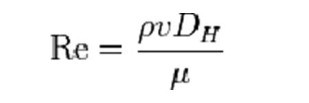
With the Re defined, pressure drop due to pipe bends can be ascertained using the equation:
where fs is the Moody friction factor in a straight pipe (a dimensionless number that relates pipe roughness, Re and friction factor, and is usually represented as a graph); p is the fluid density; u is the mean flow velocity; Rb is the bend radius; D is the tube diameter; Ø, is the bend angle; and kb is the bend loss coefficient. Values for fluid density (of most common oils and other fluids), dynamic viscosity, Moody friction factor and bend loss coefficients are all available at www.engineeringtoolbox.com along with a host of other pertinent information.
While a drop in oil pressure can be a problem, turbulent flow can be more of an issue. This is where selection of pipe unions can be of utmost importance to pump life and efficiency.
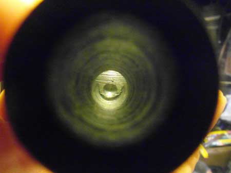
Fig. 2
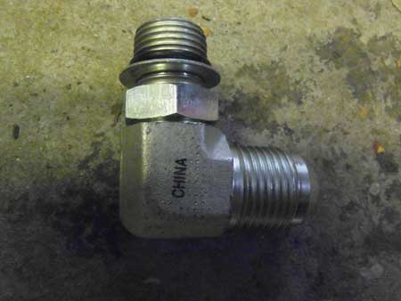
Fig. 2.1
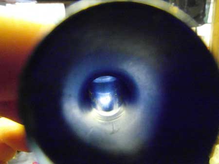
Fig. 3
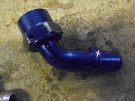
Fig. 3.1
Figs. 2 and 2.1 show a cheap and pretty nasty 90º union supplied with a dry-sump system. Admittedly it can be packaged into a very small space, but the bend is practically a right-angle turn, consisting of two intersecting drillings with a minimal radius. This is going to introduce a lot of turbulence into the flow, whereas Figs. 3 and 3.1 show a union that has a nicely radiused bend; while it will still introduce turbulence, it will not be to the same degree as the first fitting. The compact nature of the first fitting does appeal in terms of packaging, and several manufacturers now supply forged fittings, which are compact yet still retain a reasonable bend radius.
While this appears to be a minor detail, and one that could easily be overlooked, it could have a considerable impact on both the efficiency and longevity of an oil system.
Fig. 1 - Oil lines and fittings can play a far greater role in the longevity of an engine than some may think
Figs. 2 and 2.1 - A cheap oil line fitting. Note the drilled inlet and outlet, and lack of radius on the bend
Figs. 3 and 3.1 - A high-quality fitting. While it takes up more space than the previous item, flow characteristics will be far superior
Written by Lawrence Butcher
3082