Back to basics
When it comes to competition cars, more cases of overheating are caused by the installation of the vehicle heat exchanger than the choice of the heat exchanger itself. In such cases the cause of the problem is not in the selection of the matrix core or its size but in the way the unit is installed in the vehicle and the efficiency at which it gives up its heat to the passing air.
It’s easy to determine the heat rejection of an engine: simply measure the temperature of the coolant going in, that coming out, multiply by the flow rate taking into account the specific heat of the coolant mixture and you have your answer.
Alternately, you could always just measure the fuel flow rate and multiply by the heat of combustion of the fuel (around 43 MJ/kg). If you assume a heat rejection to the coolant of around 35% of this then you won’t be far out. Armed with these figures and a request for a maximum cooling area within the minimum of physical dimensions, and together with a few more facts (and an assumed ambient temperature), your supplier will service you with a suitable component to fit into your vehicle. Having ruled out poor heat exchanger design or inadequate heat exchanger size as the reasons for inadequate engine cooling, the only task now is to ensure a supply of sufficient cooling air at all vehicle speeds to have a fully functioning cooling system.
In the case of an existing saloon or sports vehicle, the location of the heat exchanger is generally more or less decided, and the only option now is to ensure that both entrance and (crucially) the cooling air exit is not restrictive. You may be able to guide the air more effectively in and out of the matrix core, but in general there are so many other chassis or engine parts in the way that any attempt at improving the airflow through the vehicle is almost impossible.
Where the installation allows much more freedom though, as in the case of a formula car or sports racing machine, the most efficient way is to carefully duct the air into and (perhaps more important) out of the heat exchanger back into the passing air as it exits the vehicle. The important areas to be addressed here are the leading edge of the entrance duct, which needs to be rounded to avoid separation of the airflow, and the diffuser section leading up to the heat exchanger core. This should be designed to slow the incoming air progressively without separating it from the guiding walls, thereby increasing its static pressure to aid the heat transfer process. Once through the core, the ducting needs to contract progressively to speed up the air again and return it to the same free-stream velocity of the air flowing past the vehicle at the exit.
In recent years designers have started to use turning vanes ahead of the entrance to the duct intake to ensure that the air spilling off the front of the vehicle is better guided into the duct, or other techniques to bleed off airflow boundary layers and thus improve the volume of air reaching the heat exchanger core. A science in itself, this is the area where vehicle aerodynamics and engine cooling start to merge.
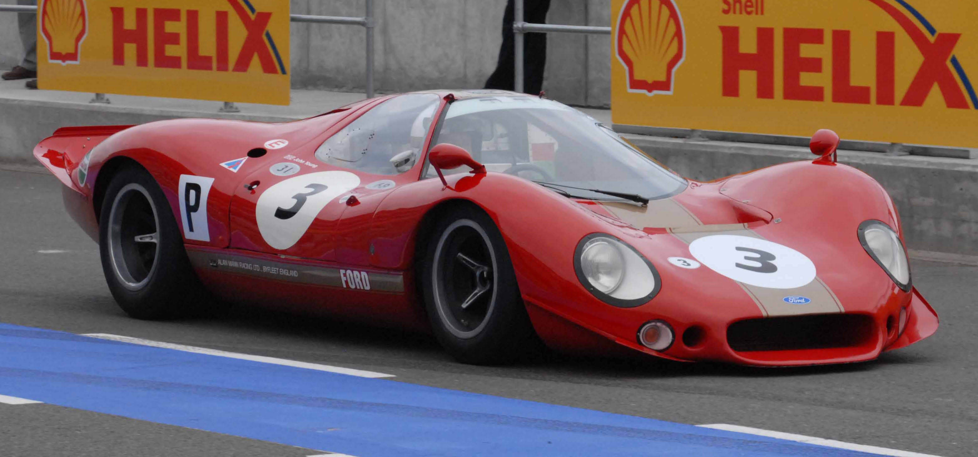 Fig. 1 - Placed at the front of the vehicle, this is still the most efficient position for the vehicle heat exchanger, if a little vulnerable
Written by John Coxon
4870