Bearing Feeds
The development of a new bearing material is undoubtedly an exacting and complex business. Likewise, the choice of a suitable lubricating fluid is not without its trials and tribulations, especially if for reasons of efficiency you are trying to break new ground in a competitive world. But bringing these together and ensuring that the right components receive precisely the correct amount of fluid throughout the engine cycle takes the problem to a higher level. The design and development of the engine bottom end is consequently enshrined in the need to ensure that a minimum oil film thickness is maintained at acceptable wear with the minimum oil flow and hence power loss to the engine.
As a journal rotates within a bearing the lubricant between them creates the well-known ‘wedge’ effect effectively separating the two. Maintaining this separation at all times at the main bearings is relatively simple, but ensuring that the big-ends do so as well is slightly more difficult.
There are two ways we can oil crankshaft bearings - feeding the fluid down the middle of the shaft and thence out to the mains and big ends in succession or, more commonly, through drillings in each main bearing housing down (or up) from the main oil gallery. The former creates minimum splash but compromises the mechanical design of the crankshaft, while the latter, although producing more splash (increasing resistance to the rotating crank), is more practical and ensures that each bearing (mains or big ends) receives, in theory, more or less the same amount of fluid at all engine speeds.
In order to transfer the oil to the big-end bearings, however, grooved main bearings are required. These carry the oil from the oil gallery feed, around the main bearings and into a drilling, carefully placed in the crankshaft and up to the con rod. A grooved bearing introduces the lubricant to the centre of the bearing from which it flows outwards, but in doing so the effective area in contact with the crank journal is reduced, along with the load-bearing capacity of the bearing. On the other hand, a plain main bearing shell has the maximum load-bearing capacity but cannot get the oil to the con rod. Clearly a compromise has to be reached.
The most practical solution is to limit the grooving in the (main) bearing, not only in its width (which controls the flow rate) but also in the extent of the groove around its circumference. Replacing the grooved lower main bearing with a plain one (to take the higher loads) while using the grooved bearing at the upper end seems to satisfy this dilemma. The big end may not receive a continuous flow of oil but so long as it is introduced during the period when the bearing load is low, the oil thus entrained should be able to maintain a minimum film thickness and prevent surface-to-surface contact.
Minimising the oil flow and reducing engine friction but maintaining the minimum oil film thickness at acceptable wear rates, and at all engine operating conditions? Welcome to the wonderful world of power unit engineering!
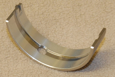
Fig. 1 - Grooved main bearing shell
Written by John Coxon
4730