Bearing the strain
When discussing bearings it is sometimes easier to limit such studies to those of the crankshaft mains and con rod (both big and little ends). In more modern times the turbocharger bearing is perhaps attracting more interest, so these days we consider those of the camshaft only rarely. Running at half engine speed and not particularly highly loaded, the bearing design is probably dictated mostly by the process of assembling the cam into the engine.
Inserted from the front or rear of the engine, the bearing diameter has to be more than twice the cam centre line to nose height. However, in the case of overhead cams, where the engine height may be critical, separate bearing caps gives the opportunity to remove this restriction, and the limitation is more likely down to loading and the materials used. In this case, from the handful of cams I’ve surveyed recently, for overhead cams using separate cam bearing caps, journal sizes can be anywhere of the order of 18-25 mm for lightweight contemporary designs.
Going back in history, camshaft bearings were effectively just smaller versions of main or big-end designs. Babbitt materials were used on vintage units and, when shell bearing designs became available, some form of aluminium-tin mixture (usually around 20% tin) would be deposited directly onto a steel backing. These would be dropped into place during assembly and, if memory serves, they rarely failed in any significant way so long as the flow of lube oil was maintained.
In more modern times, and to save cost without impairing durability, cam journals are more likely to run directly in the aluminium cylinder head for production engines. Presumably the spare graphite in the structure of a typical cast-iron cam, and the silicon in the cylinder head aluminium mix being compatible, gives no need to introduce yet another unnecessary component, and this of course will no doubt also keep those in charge of the finances happy as well.
Lately though, what with the relentless push to reduce fuel consumption, engine technology – particularly with respect to valve gear – is taking on an interesting twist. Although the cam journals in the valvetrain contribute little to the overall friction, efforts are being made to reduce this friction wherever possible. Thus on camshafts, plain journals are now being replaced by small roller bearing technology, and despite the obvious increase in complexity and commensurate cost, the difficulties of designing small split-roller cages are being overcome.
For those not already in the know, the big advantage of a roller bearing over that of the traditional plain bearing is that it eliminates the boundary layer effect when relative movement between shaft and journal is low. Theoretically, a roller bearing has point contact only, and with no sliding (just rotation) friction is low.
But when it comes to camshafts some ingenuity is needed. A roller bearing must have three elements – an inner race against which the rollers move, the rollers themselves held apart by a cage and the outer race. In the case of this latest cam roller bearing design the inner race is that of the camshaft journals, while the 18 or so 1 mm diameter rollers are held in a rigid plastic cage split so that it can be assembled around the cam journal. The outer surface, rather than relying on the aluminium of the cylinder head, is a pair of 0.7 mm thick steel shells that locate in the cylinder head using the hole drilled for the oil feed.
This ensures that the outer shell is correctly aligned and the oil feed is not restricted through poor build assembly. More interestingly, however, the split line of the bearing doesn’t follow that of the bearing cap. To ensure that the rollers are disturbed as little as possible when crossing this split line, the outer bearing is split in the shape of a sine curve, as shown in Fig. 1.
Perhaps this is the shape of cam bearings of the future?
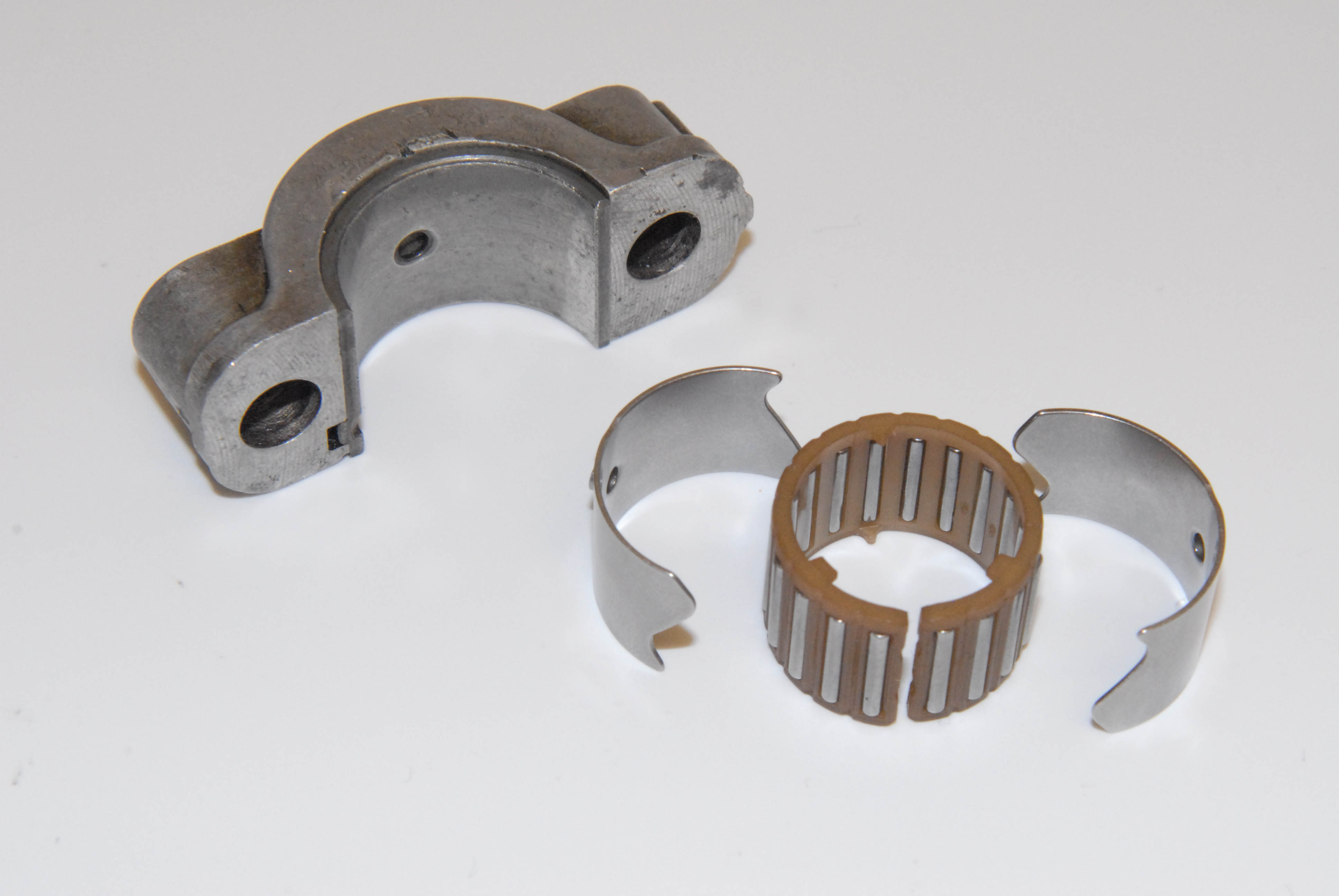 Fig. 1 - Early aluminium-tin camshaft bearing in its upper housing alongside a more modern equivalent
Written by John Coxon
6291