Cast-in pipes
 Engine developers have always been regarded as 'strange' people. The reason for this is unclear, although the fact that we tend not to come across as 'straightforward thinking' people in the eyes of others may have something to do with it. But then finding non-straightforward solutions to problems is part of the engine developer's job.
One of the most interesting things about an engine is that its various systems need to cooperate in order to achieve the engine's overall function - providing power to the vehicles we race in. These systems all have their own integrated function, for which the engine provides their respective infrastructures. Looking at the fluids in the engine - coolant, oil and fuel - this infrastructure means all of the connections, ports, channels and cavities creating the system's boundaries.
Traditionally, transporting fluids throughout the engine block has been via drillings and cast cavities - sometimes combined with lines, pipes or tubes - and their connections. Due to their simplicity, drillings have been the most favoured method, assuming accessibility for the drilling tool. When this accessibility is not available, however, or the geometry gets too complex, cast cavities are often used, and these are widely used in coolant jackets in cylinder heads for example.
It gets more difficult though when the geometries get too small and/or too complex to cast. For example, it's often not possible to produce oil channels using sand cores. The reason for this is the stability of the sand core, where certain minimum dimensions are required in order to prevent core breakages during the production process.
So, wouldn't it be worth it investigating other solutions to transporting fluids through the engine block casting? Another typical issue requiring a possible alternative solution is stress concentration at locations where drillings cross through highly loaded areas of the block, such as the bulkhead areas.
As a general engineering rule of thumb, every engine designer will try to design all drillings away from these areas, but sometimes this isn't possible. For inline dohc engines, typically no drillings are located in the bulkhead region other then those from the main oil rifle to the crankshaft bore. Typically these need to stay away from the threads of the main bearing bolt, so as not to increase stress levels. Vertical drillings from the main oil rifle feed the cylinder head with its camshafts, through holes in the head gasket.
With inline engines using in-block camshafts though it's a different story, as it is for vee engines with the oil pressure pumps located alongside the crankcase. In these designs the pressure drillings need to cross the bulkhead at least once, to get the oil from pump to main oil rifle.
Investigations show that a drilling at right angles through the bulkhead increases the local stress level in the bulkhead by about a factor of nine. Angled drillings will reduce this to a factor of three compared to no drillings at all.
If relocating these drillings does not seem possible, one could take several measures to reduce the stresses to acceptable levels, but unfortunately in almost all cases these will lead to increased wall thicknesses around the drilling and therefore additional mass and engine length. Are there no other possibilities?
Some years ago I was involved in a development project to cast a structure of pipes, the so-called pressurised oil feed structure. This consisted of a number of curved steel pipes to create the oil system for the crankcase. The block was an inline, six-cylinder cast-iron item with an in-block camshaft. The main oil rifle was on the exhaust side of the engine and the single camshaft at the intake side, both supported by seven plain bearings, each requiring their own oil feed. This meant the task was to install seven pipes into a sand core package that could withstand the casting process itself.
It was decided to drill the main oil rifle, due to the risk of leaks between the main oil rifle and the other seven pipes when integrating them. The oil system needed to be fully open and cleanable after the block was cast, and the existing machining operation was not allowed to be significantly changed. This concept was brought to the stage where a couple of engines ran successfully in the test bed, but did not make it to series production because the concept was not fully developed.
Let me describe on some of the lessons learned with this concept, which should be able to be overcome given sufficient time and attention.
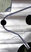
• Effective closure of the pipes before the casting process. The pipes were extended significantly into the crankshaft bore sand cores (see image) to prevent them from filling up with fluid iron during the casting process.
• Fusion between pipe and cast material. To prevent leaks and uncontrolled cavities between pipe and cast base material, a secure connection between both materials during the pouring phase was required.
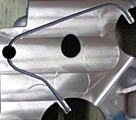
As can be seen in the image here, the oil feed makes a slight bend in the path from the main bearing bore (lower right corner) to the main oil rifle (left middle), in order to maintain sufficient clearance with the main crankshaft bore bolts. From the main oil rifle the oil feed heads up, through the bulkhead, to the camshaft bore (not visible in the picture).
The engines that ran with this concept did run successfully, providing the confidence that the concept is feasible, and therefore able to create some additional freedom for crankcase oil system design. Again, the major goal is to feed the oil system through low loaded areas of the crankcase, not strictly limited to the geometry of the cast material itself. If required, this concept would allow the pipes to exit the cast structure where applicable.
Together with the hybrid casting concept, this could open new thinking about engine block design.
Fig. 1 - Cast-in oil system concept in a cast-iron engine block's main bulkhead
Written by Dieter van der Put
4988