KERS - epicyclic gearing
 Connected between the flywheel and the continuously variable transmission of the Flybrid, mechanical KERS is an epicyclic gear system, the focus of this article.
Epicyclic gearing is a gear system that consists of one or more planet gears, rotating about a central sun gear. Typically, the planet gears are mounted on a movable arm or carrier which itself may rotate relative to the sun gear. Epicyclic gearing systems may also incorporate the use of an outer ring gear or annulus, which meshes with the planet gears.
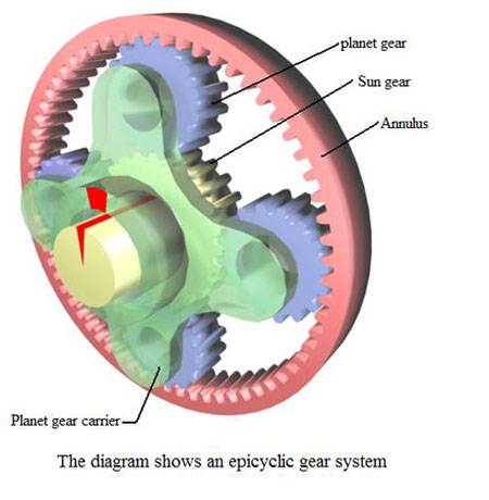
The three basic components of the epicyclic gear system are:
Sun gear: This is the central gear.
Planet carrier: Holds one or more peripheral planet gears, of the same size, meshed with the sun gear.
Annulus: An outer ring with inward-facing teeth that meshes with the planet gear or gears.
In many epicyclic gearing systems, one of these three basic components is held stationary. One of the two remaining components is described as an input, providing power to the system. The other moveable component is described as an output, receiving power from the system. The ratio of input rotation to output rotation is dependent upon the number of teeth in each gear, and upon which component is held stationary.
The gear ratio in an epicyclic gearing system is not intuitive, because there are several ways in which an input rotation can be converted into an output rotation. One situation is when the planetary gear carrier is held stationary, and the sun gear is used as input. In this case, the planetary gears simply rotate about their own axes at a rate determined by the number of teeth on each gear.
If the sun gear has S-teeth, and each planet gear has P-teeth, then the ratio is equal to S/P. For example, if the sun gear has 24 teeth, and each planet gear has 16 teeth, then the ratio is 24/16 (or 3/2). This means that one clockwise rotation of the sun gear produces one and a half (1.5) anti-clockwise rotations of the planet gear.
The rotation of the planet gears, drives the annulus in a corresponding ratio. If the annulus has A-teeth, then the annulus will rotate by P/A turns for each turn of the planet gears. For example, if the annulus has 64 teeth, and the planet gear has 16 teeth, one anti-clockwise turn of a planet gear results in a ratio of 16/64, or one quarter (1/4) of an anti-clockwise rotation of the annulus.
Therefore, with the planet carrier locked, one rotation of the sun gear results in S/A rotations of the annulus. That is if the annulus has 64 teeth, and the sun gear has 24 teeth, one clockwise turn of a sun gear results in 24/64, or 3/8 of a rotation of the annulus.
The annulus may also be held fixed, with input provided to the planet gear carrier. Output rotation is then produced by the sun gear. This configuration will produce an increase in gear ratio, equal to 1+A/S.
Alternatively, if the annulus is held stationary and the sun gear is used as the input, the planet carrier will be the output. The gear ratio in this case will be 1/(1+A/S). This would be the lowest gear ratio attainable with an epicyclic gear train.
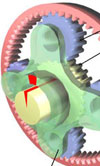
Fig. 1 - The diagram shows an epicyclic gear system.
Written by Eric Smart
4628