Crankshaft bearing selection
Although the theory of designing crankshaft bearings is now so much more sophisticated, the practice of building the engine to the correct clearances is still a bit of a challenge. With the running clearance between bearing and journal measured in microns, and the difference between too little (resulting in seizure) and too much, leading to excessive wear and hence early failure, the selection of this gap is always likely to be critical.
Typically a cylinder block machining line may machine, say, 100 blocks in an eight-hour shift. During this time the block would be line-bored to, say, 80.00 mm diameter and then fine-honed to the final dimensions of 80.014-80.032 mm. The limits to manufacture therefore would be stated as being 80.014 mm at the maximum metal condition and 80.032 mm at its largest or minimum metal condition, a difference of 18 microns. The crankshaft line, however, making roughly the same number of crankshafts in the same time period, may be grinding the main bearing journals to a tolerance close to ±0.010 mm (10 microns). Here the journal size, once ground and polished, would be, say, 75.000 mm at its maximum size and 74.980 mm at its smallest. Given that we can machine these components to such accuracies, it still requires a system of selective assembly to build engines to the correct running clearances. In these days of mass production, where parts are purposely designed to tolerate large variations in finished dimensions, this is an expensive but nevertheless the only realistic option.
As part of the design method and the limitations placed on them by the chosen supplier and/or legislation, engine designers will have selected the type of bearing for the application. Durability trials will establish the limits of the bearing-to-journal clearance, which has to allow sufficient oil to flow to cool the surfaces but at the same time generate enough pressure to keep the surfaces apart throughout the full duration of the sign-off tests and hence proposed engine life. Using low-viscosity engine lubricants, and with clearances strictly controlled to a matter of plus or minus a few microns, the bearing selection procedure still has to be simple.
The process starts out at the manufacturing stage. For the cylinder block this means that after the line boring and honing operation, each main bearing will be gauged to determine its size. Since our total machining tolerance is of the order of ±0.018 mm, the possible bearing shell outside diameters will be split into two or three different bands, each with a band width of around 0.0040 mm and each one represented by a code. This data will then be transferred to side of the block to be read either manually or by machine at the assembly stage.
Likewise, the crankshaft journal diameter will have been also measured and the sizes coded, and again this data will have been etched in some way on the crankshaft, usually on the machined face at one end.
To select the precise main bearings it must be remembered that although visually they are the same, the upper and lower main bearings will have different part numbers, with each bearing colour-coded with up to four or five different colours – typically blue, green, yellow, brown and so on – reflecting their exact size. Selecting the correct bearing using the appropriate colour(s) from a matrix that lists main bearing bore size against the exact journal diameter is therefore simple, remembering of course that where differing colours are demanded, these can be fitted in either upper or lower bearing positions.
It may sound complex but believe me, it is much easier to do than explain.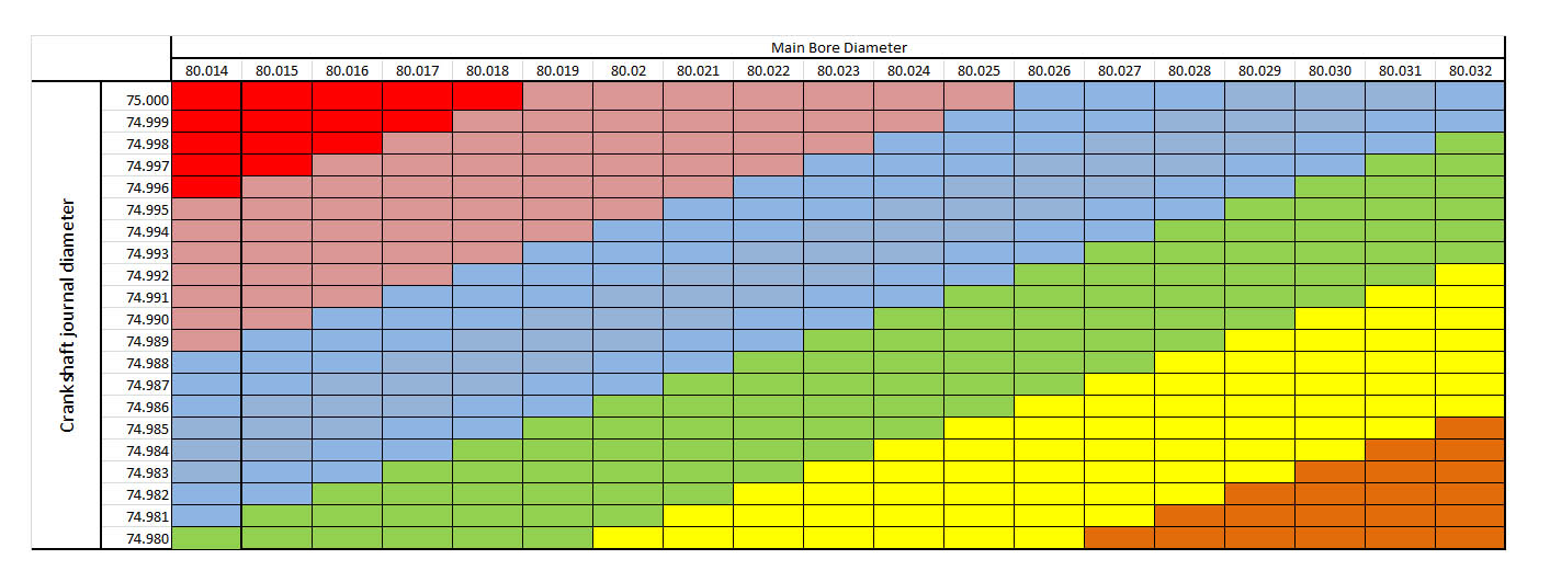 Fig. 1 - Typical bearing selection matrix
Written by John Coxon