Slip sliding away
Friction in an engine means different things to different people. To some it equates to lost power; to others it is lost fuel economy, while to the environmentally aware it represents increased engine emissions, and so faced with these it is little wonder that great emphasis is placed on reducing it. Low-tension oil control rings, minimal sized bearings – both big end and mains – or variable flow oil pumps to match precisely the oil required by the bearings and no more, these are all examples of engine developments designed to boost engine efficiency by reducing friction. So when it comes to improving the efficiency of the valvetrain (the other major source of friction) it might be tempting to replace the typical sliding tappet with a roller tappet or roller lever.
Using simple theoretical analysis it’s easy to see why. In any sliding element, as soon as the boundary friction has been overcome and the friction drops then, as the relative movement necessary to generate the wedge of oil increases, the resistance to movement (equivalent to friction) actually starts to build up again. In the case of rolling contact where, strictly speaking, there is only line contact across the cam-follower mating surface, the absence of relative movement suggests the absence of friction or its inevitable result, wear.
From the outset though, it must be appreciated that rolling contact components are generally much larger than sliding ones and are therefore likely to be much heavier, in general making them useful only in relatively low-revving larger engines as opposed to the much smaller faster-revving units that use sliding technology.
Apart from the apparent reduced friction, there are of course other issues. For example, a rolling contact increases the contact stresses where the cam meets the follower. Anyone who understands the theory of Hertzian stresses will realise that the maximum stress in the camshaft will occur just slightly below the surface of the cam, and is a function of the radius of both the follower and the instantaneous radius of the cam at the contact point. The larger the roller, the lower the Hertzian stress, but the larger the roller then the heavier it is likely to be and the more difficult it will be to incorporate it within the engine.
The presence of the roller will also change the valve lift curve, simply as a result of the geometries involved, and while it may be possible to generate more rapid valve opening by using negative-radius cam profiles, this further increases the surface stresses, so even higher quality fatigue properties on the cam material are needed to prevent the formation of surface pitting.
While the analysis may also assume little or no slip between the rolling element and the cam, in reality that may not always be case. Slip is almost unavoidable, as a result of elastic deformation of the parts. This increases the surface area over which these forces are applied, reducing the contact pressure and increasing the likelihood of slippage or skidding. Minimising distortion by using materials with a higher Young’s modulus will increase contact pressure but will also increase the levels of Hertzian stress. As ever in the design process, the solution will inevitably fall somewhere between the two.
Whichever way you look at it, roller followers may sound like a good idea at the outset, but like many good ideas the exploitation of the benefits may be down to the matter of detail design.
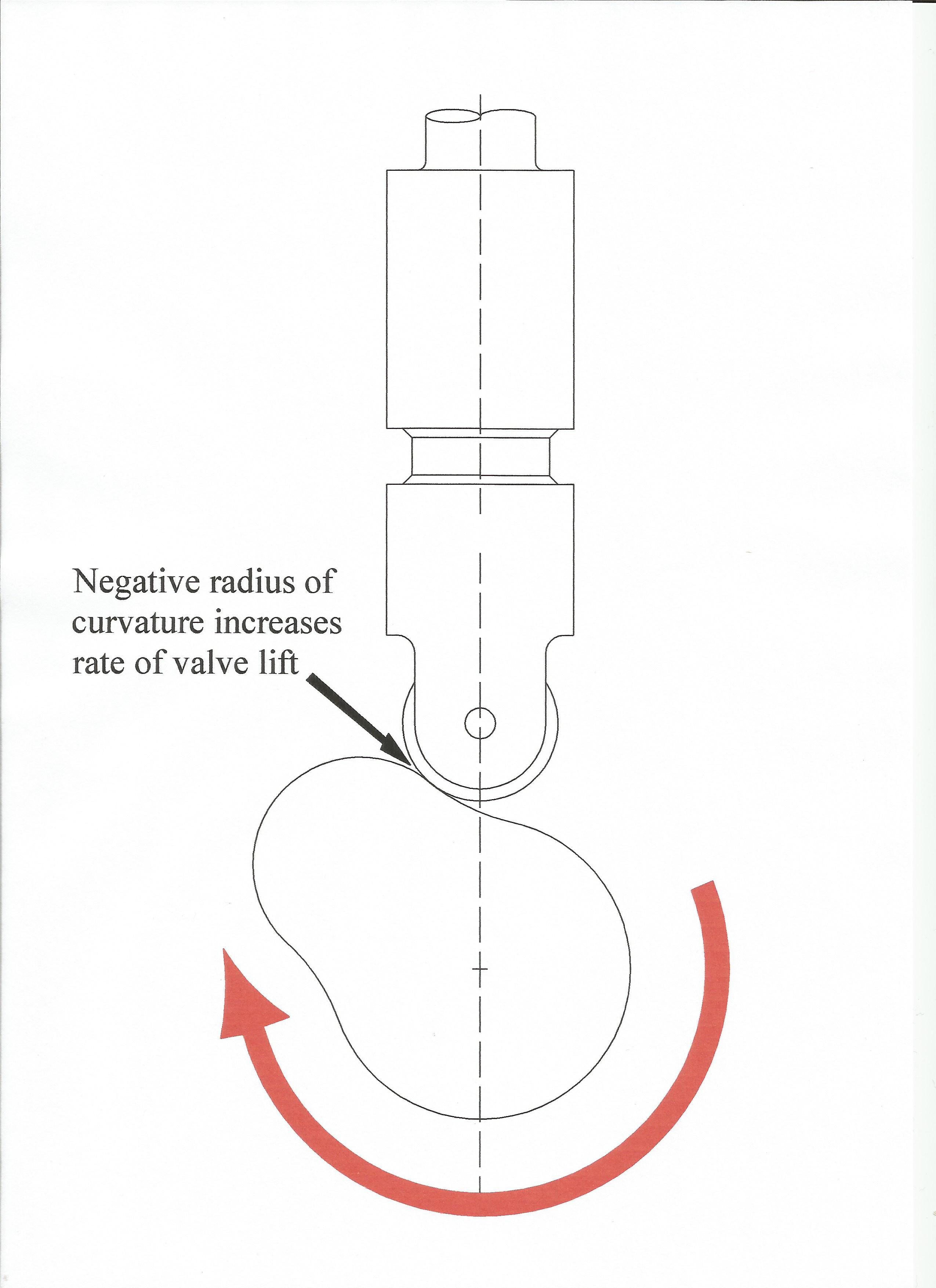 Fig. 1 - Cam and roller follower
Written by John Coxon
11845