Asymmetrical profiles
"What goes up must come down." I'm sure we've all heard that at some time, and a true enough statement most of the time (but not as it seems to gasoline prices at the pump). But what has this to do with cam design, I hear you ask? Well, if you substitute the words 'goes up' for 'opens' and 'come down' for 'closes' you can begin to see what I'm getting at.
The fact is that, in designing a cam profile, we have to lift the valve assembly off the valve seat, accelerate it open to its maximum velocity and then slow it down, bringing it to a halt before accelerating it back in the opposite direction, then slowing it down and eventually landing it gently back on its seat. A simple enough process, you might say, but one nevertheless that has challenged and is still challenging designers.
Take a 'simple' polynominal profile for instance. With the profile described by a sixth-order polynomial

and ignoring any ramps, for our boundary conditions when the valve is closed we have y (displacement) = 0, its derivative with respect to angle (velocity) dy/dx = 0, as well as its second derivative (acceleration). At the other boundary when y is a maximum and x = 0 we have velocity = 0 and acceleration = 0.
Differentiating the equation with respect to x to produces equations for velocity, acceleration and jerk (the third derivative) and substituting in the boundary conditions we come up with a series of simultaneous equations, which need to be solved. Once solved, the equations of displacement, velocity, acceleration (and jerk - the third derivative) can be written and the half-cam profile produced which solves all the given boundary conditions. Extending the power of the polynomial beyond six -perhaps as far as 12, 14, 16, even 24 - and varying the individual coefficients will eventually give you a half profile, which will describe (hopefully) more or less what you want.
Needless to say, using a hand-driven calculator with pencil and paper, and quite a lot of trial and error, the process was only for those of a certain disposition and took many days or weeks to perfect - and even then you still only had half a cam profile. It was little wonder therefore, having got this far, that the simplest approach was one of reflecting the profile about the 'y' axis and bringing the valve down in the same way as it went up.
These days all this is done by computer and the various excellent cam design software that is available, such that the role of the cam designer is perhaps no longer so specialised. In opening the valve we might want to do that as quickly as possible to generate pulse activity in the induction system or exhaust pipe. However, it is not always the case that we want to close it as quickly; hence the idea of the asymmetric cam. In some cases we might want to minimise valve bounce by introducing the valve more gently to its seat. Or in other applications it might be necessary to keep the valve open a little longer, introducing more air and swirl into the chamber during the combustion process. Either way it might be beneficial to use a different closing profile to that of the opening one.
What goes up, must come down - but not necessarily in the same way.
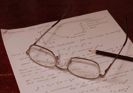
Fig. 1 - Calculating profiles using pencil and paper was not for the faint-hearted
Written by John Coxon