That other camshaft
It is perhaps easy to forget that while in most gasoline engines the function of the camshaft is solely to open and close the intake and exhaust valves, in others - particularly the more modern direct injection designs - cams are part of the fuel system. Diesel engines, of course, have always injected the fuel directly into the cylinder, and the most convenient way to do that (converting the rotary motion of the crankshaft into one of a reciprocating nature of a high-pressure pump) is to use a cam.
The limitations of these injectors which both injected and metered the fuel eventually gave way to the common rail system, in which the method of increasing the pressure of the fuel and then injecting it into the cylinder were divorced from each other. Unlike the jerk-pump approach, multiple injections were now possible, and the opportunity to control the combustion more precisely - indeed, to supply multiple injection per cycle - was at last achievable. Advances to the thus named 'common rail' diesel engine resulted inevitably in the ultimate in spark ignition units, the GDI, or gasoline direct injection system.
But while the function of the intake and exhaust camshaft is to open the valves as quickly as possible - to hold them fully open for the required duration and then close them again just as quickly, without valve bounce or loss of control - the requirements placed on the fuel cam of a GDI engine are in some ways significantly different but in others surprisingly similar. So while the intake and exhaust valves are needed to pass as much air as possible, the same goes for the reciprocating fuel pump.
In doing so though, and delivering something like 0.5-1.1 cm3 per stroke at 200-plus bar delivery pressure, the forces on the fuel cam are often considerably greater. Unlike the intake/exhaust cams, the fuel cam works in a different way and it is only on the upstroke when it is moving the fluid. Also, the greater the number of lobes on the cam - whether this be two, three or four - the greater the fluid flow. At the same time, the velocity of the stroke is limited by the forces involved, the diameter of the flat tappet follow and in particular by the limiting minimum oil film thickness between the cam and its follower.
Another issue to consider is the position of the pump. Positioning it at the end of the intake or exhaust cam often introduces packaging concerns and will increase the centre-of-gravity height of the installation, as well as limiting the fuel flow since the cam only runs at half engine speed. Likewise, mounting it lower down or between the cylinder heads of a vee engine and running it at crankshaft speeds can introduce concerns of inadequate lubrication or ensuring the cam follower interface entrainment velocities are not excessive. Running at high crankshaft type speeds will result in oil being centrifuged off the rotating cam lobes, resulting in a lack of lubrication.
While the combustion engineer can only marvel at the increase in bmep from his direct injection designs, the cam designer has more than just a few more issues to contend with.
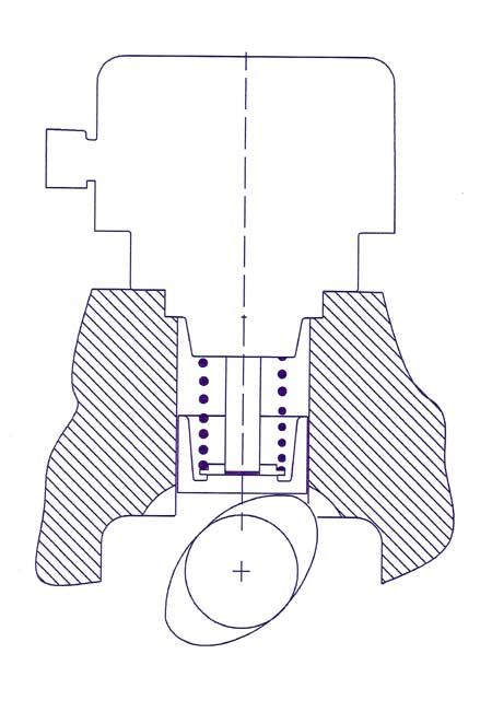
Fig. 1 - Two-lobe DI fuel pump drive
Written by John Coxon