Big End Design
 After the article last month which looked briefly at the small end of the con rod, we shall look this month at the opposite end of the con rod. Referred to as the ‘big end’ or ‘large end’ this end of the con rod houses the bearings which transfer the piston and con rod loads to the crankshaft. Again we shall concentrate on the type of con rod found in the four-stroke engine typical of Formula One and many other racing series.
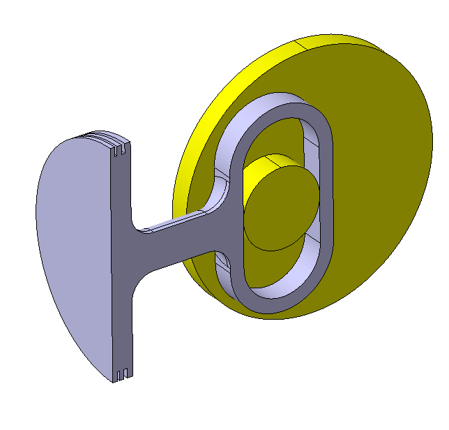
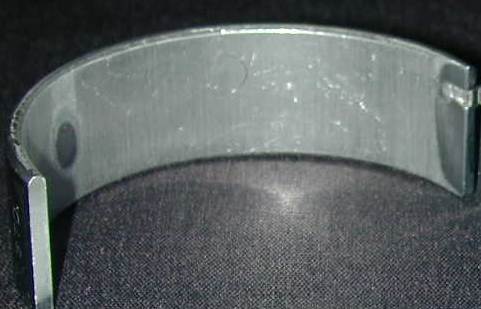
One of the main jobs that the big end has to do is to house and retain the bearing which is almost exclusively of the plain journal type made of two individual halves. The most popular method by which these are retained is by the use of ‘tags’ which are pressed or stamped into the bearings. Each part of the con rod (which we shall refer to as the cap and the blade) has a corresponding machined slot. An alternative method is to pin the bearing but, given the thickness of the big end bearing shells used currently, this method of bearing retention lends itself much better to the main bearings in the cylinder block. I have also seen con rod designs which rely solely on the heavy interference of the bearing in the big end. However, I don’t know if these have been successfully raced.
In Formula One, where the bearings are very thin, attention has to be paid to the stiffness of the material around the bearing such that it provides sufficient support to the bearing. If the bearing is not adequately supported by the surrounding material it tends to push away under load and thus overloads the better supported parts of the bearing leading to premature wear and failure.
If the design philosophy of the con rod requires that the small end is positively lubricated, oil is supplied via a drilling between the two ends of the con rod. Clearly the oil feed to the drilling must be via a hole in the bearing and the location of this hole is, in general, not directly in line with the drilling between the big and small ends of the con rod. In this case, the drilling is supplied via a slot machined into the bearing surface of the con rod blade which extends between the drilling and the feed holes in the bearing. It is clear that the bearing is unsupported where such slots are provided and this has to be taken into account when sizing the bearing and designing the con rod.
In designing the con rod, there are various different ideas applied to the design of the con rod cap, and these employ polar opposite philosophies. It is popular to provide quite a deep cap which is very stiff with the aim of maintaining a circular bearing housing. The stiffness of the cap comes at the expense of increased mass which consequently leads to increased rotating crank assembly inertia. The mass and stiffness are the subject of a trade off to arrive at an acceptable compromise. An alternative is to provide a deliberately flexible cap, where one is resigned to the fact that the cap will deflect and wrap around the crankpin thereby limiting the deflection of the conrod. This is less popular than the stiff cap philosophy, but the benefit of this flexible design approach is reduced mass and inertia.
Next month we shall look at the remaining aspect of the big end – the joint face design and the joint itself.
Written by Wayne Ward.
4827