The cooling fan
Although a car properly designed for speed should never have any problems with cooling, there are times when the lack of forward motion can limit the amount of heat dissipated through its radiator. In earlier times, simple two- or four-blade fans would be powered directly via a v-shaped belt from the engine crankshaft, but these days when the cooling limit from the forward motion of the vehicle has been reached, the electric fan normally takes over. Used in competition - for instance in rally cars when the engine idles for long periods of time, or in trials cars if the forward speed is very low and the engine under load - its design may appear simple at first, but even when bought as an 'off-the-shelf' unit its installation can present problems for the unwary.
To understand many of the issues, it's as well to look at what we are trying to achieve in drawing or pushing air through a vehicle's radiator. First and foremost, a cooling fan is an air mover, designed to move relatively large amounts of air against little or no back-pressure. For this type of application an axial-flow air mover is ideal.
Having selected the type of fan most suited to the application, it is now important to design it so that it imparts to the air stream a uniform velocity and pressure over its entire area. And to ensure that the radiator is working as efficiently as possible it is imperative to select the largest fan diameter that can be accommodated. Sometimes, because of the size or shape of the radiator or its location, there is insufficient room for a single large unit and therefore two smaller ones have to be substituted. Be aware, however, that even if you ignore the blockage effect of the central hub motor, it takes for instance two 8 in diameter fans to give the same cooling performance as one only 3 in bigger.
Although apparently simple, the design of a fan is a lot more complicated than many might think. First, each individual blade will be narrower towards the tip where the velocity is highest and progressively widen towards the central hub. Also, the blade profile, an aerofoil in shape, will be selected for its optimum efficiency of lift versus drag over the anticipated speed range, and the blade will twist from a minimum angle of incidence with the airflow at the tip to a maximum at the other end as it adjoins the central hub. In this way, the reducing velocity of the blade as we move in from the tip is compensated for by the increasing angle of incidence to the airflow and a uniform velocity and pressure across the outlet results.
But of course, once you have created your uniform distributed airflow in the most efficient way, the last thing you want is to let it escape or come from a place where it doesn't pass through the radiator matrix. Shrouding the zone between the radiator and the rotating tip of the fan is therefore imperative, while at the same time making sure that the pressure at the outlet is not restricted to any degree. Such restrictions, for instance the close proximity of an engine, may cause the airflow to stall or circulate around only the blade and not through the radiator core.
The electric fan may be ubiquitous in modern vehicles but it still takes careful design and installation to get the best out of it.
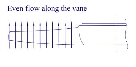
Fig. 1 - The fan blade must generate a uniform velocity and pressure of the airstream over the entire area
Written by John Coxon