Methods of fitting heavy metal to counterweights, part 2
 In the previous article on the subject of adding tungsten counterweighting to crankshafts, we looked at one of the more widely adopted methods where cylinders of tungsten alloy are pressed or shrunk into specifically machined bores in the counterweights. The conclusion that many crankshaft manufacturers and design engineers have come to is that this is a reasonably effective method of adding tungsten while affording generous safety factors against failure. It is also simple from a practical point of view.
There is another popular option though, which is to install threaded inserts either radially inwards or in that general direction, i.e. parallel to a line joining the counterweight mass centre and the closest point on the crank axis. In a thick crankshaft counterweight, it is easy to imagine a series of holes, drilled and tapped radially inwards from the outside radius of the crankshaft. Into each of these can be screwed a tungsten insert provided with the appropriate thread.
The idea is very simple, but there are considerable forces acting radially outwards on the tungsten due to its mass, so there are a number of important considerations to account for in terms of component stresses before deciding that this method is the one for your application.
First, the engineer needs to be satisfied that the insert isn't going to come undone, as some troublesome fasteners tend to do if they lose preload. These will definitely be more trouble than the average loose bolt should they decide to exit the crank!
There are several chemical methods - thread-locking compounds, bearing-retaining compounds, high-temperature adhesives - that might be used to lock the insert in place. However, a popular method is to 'stake' the inserts in place by mechanically deforming the insert, crankshaft or both, often by making a series of marks using a hammer and centre punch around the periphery of the insert at the outside of the counterweight.
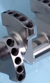
The photograph here shows a V10 Formula One crankshaft from several years ago that was designed to be used with radial-type inserts. The inserts to be used with this crankshaft (not installed) aren't true radial inserts, but instead run parallel to the plane through the crank axis and crankpin they are balancing. As can be seen from the photo, the inserts are short pieces, confined to the thick 'rim' of the counterweight. Another important consideration is to calculate whether the length of engaged thread is enough to prevent thread stripping when the insert is under maximum load.
There is the more conservative (and costly) option of welding a cap over the end of the hole, but this also serves to displace tungsten from the outer radius of the counterweight, where it is most effective.
An alternative to the radial-threaded tungsten insert is one that is installed in a hole through the counterweight drilled perpendicular to a plane containing the crank axis and the counterweight into which the insert is to be installed. This method allows for one or two tungsten bars to be inserted into threaded holes, and then to be staked or otherwise kept in place by welded caps again. This method is not as popular as the radial type insert.
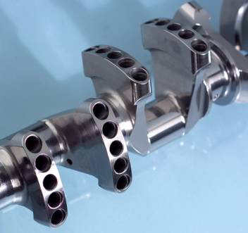
Fig. 1 - With 50 tungsten inserts, the careful assembly of this V10 crankshaft is critical to reliability (Courtesy of Pankl)
Written by Wayne Ward
5984