Nose feed
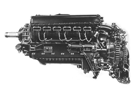
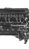 The use of nose-feed crankshafts has been mentioned before, both in these RET-Monitor articles and in Race Engine Technology magazine issue 49. It is certainly not a new concept, having been used in the Rolls-Royce Merlin engines* with great success, nor is their use limited to the highest level of motor racing, having been used with success in LM P1 and LM P2 sportscar racing as well as some production motorcycle engines.
The idea behind them is simple: the oil is introduced to the crankshaft along its centreline rather than radially inwards via the main bearings. In feeding the oil into the crankshaft at a point on its axis, we lower the oil pressure requirement.
There are other advantages to nose-feed crankshafts. We can use the centrifugal action of the rapidly rotating shaft to improve the quality of the oil feed to the bearings, in terms of minimising both aeration and hard particles that may have got into the oil system. We may have a three-phase system, of which we want only the oil (the other two being solid debris and air) to be sent to the bearings. Centrifuges are a common industrial method of separating all kinds of materials, and the cavity of a nose-feed crankshaft that receives the oil is, in effect, a small centrifuge that we can use to help separate the oil from the other phases.
If we can get the fluid to spin at a high enough rate then we can separate the oil in a short length. If we ignore the issue of having solid debris for a moment, it is easy to imagine that the oil, being several hundred times more dense than any air entrained within, will tend to travel radially outwards, forcing the air radially inwards towards the centreline of the crankshaft. This is the same simple principle that governs rotary mechanical air-oil separators that can sometimes be found on race engines, except that the proportion of oil and air are much different in those devices.
If we extend the same principle a little further, this time including the solid debris that might have found its way through a damaged filter or might have been present in the oil system at first build, then this should make its way to the outside wall of the nose-feed cavity. Owing to the smaller difference in density of the oil and debris compared to the oil and air, and taking into account the viscous drag that the oil imparts on the debris, the process of centrifugal separation is not as rapid when trying to separate debris as it is with air.
There is another issue to consider once we have grasped the principles of centrifugal separation and convinced ourselves that we can make it work - how do we ensure that neither air nor debris are likely to enter the galleries that connect the nose-feed cavity to the main and big-end bearings? This will be the subject of further articles.
* Rubbra, A.A., "Rolls-Royce Piston Aero Engines - a designer remembers", Historical Series no 16 :Rolls Royce Heritage Trust, 1990. ISBN 1-8729-2200-7
Fig. 1 - Operating on the same principles as a swing carousel, the nose-feed oil system of a crank can separate oil, air and solid debris
Written by Wayne Ward
4177