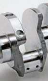
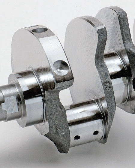
Oil-hole details
 The fatigue behaviour of a crankshaft is dictated by the service loads it is expected to cope with, its manufacture and its geometry. In numerous articles concerning crankshafts, surface treatments and materials, RET-Monitor has stressed the critical importance of compressive residual stresses for increasing fatigue life, and it is here that the correct selection of material, heat treatment and further processing is of utmost importance.
In terms of geometry, there are two types of crankshaft design features that most often prove to be the initiation site of fatigue damage. The first are the fillet radii which we find on the crankpins and main bearing journals. The oil hole exits on the crankpins, and main bearing journals are also common sites for fatigue damage initiation, so it is these that we shall look at a little more closely in this article.
The geometry of the oil-hole exit and the level of surface stress here is critical to providing an adequate safety factor against failure. The crankshaft is stressed in both torsion and bending. In both of these cases the stresses occur at the extreme fibre of the material.
So, if we imagine a beam in bending with a vertical load applied somewhere along its length, we can expect to find that the maximum tensile or compressive stresses will be found at the top and bottom of the beam. In terms of a cylinder in pure torsion, the maximum shear stress occurs at the surface.
Other than simplicity, there is little that could be recommended in simply drilling the oil hole in the correct position. By doing this, a sharp edge would be provided at the point of maximum shear stress and, owing to the resulting stress concentration due to the hole, this point will have a very high level of stress. It is common therefore to provide a nice radius on the oil-hole exit, and this can be done carefully by hand or as part of the machining of the crankshaft.
It is important to select the appropriate stage during manufacture at which to carry out this procedure. If the material is removed after nitride hardening, the surface of the crankshaft will be robbed of its protective compressive residual stresses. It is better then to provide the radius before surface hardening and then to polish the area at a later stage, removing very little of the layer imbued with the compressive stresses.
There are other solutions to the radius provided on oil-hole exits, and on production crankshafts we commonly find a simple chamfer, but this is not as effective as a properly formed radius. Other simple milling operations are used for racing crankshafts which are thought by those using them to be as effective as the radius on an oil-hole exit, but which are not as costly in terms of manufacture.
Textbooks inform us that the maximum shear stresses occur at an angle of 45º to the axis of a cylinder loaded in torsion. We can therefore resort to more elaborate schemes for removing material from the oil-hole exit, and these include material being removed at an angle of 45º to the crankpin or main journal axes.
Fig. 1 - Poorly finished oil-hole exits can lead to early crankshaft failure
Written by Wayne Ward
7614