The DeltaWing
For anyone who hasn’t seen the Nissan DeltaWing car, you would do well to look it up, as there can have be few more adventurous car designs in recent times. This was no rolling concept car, but raced at Le Mans. Its ethos was very ambitious – to be competitive with existing LM P2 cars but with half the power output and using half the fuel. Its unusual form – extremely narrow and low – meant it had a much lower power requirement and could therefore use a much smaller engine, which used much less fuel than the larger LM P2 prototypes which it set itself the challenge of matching. The innovation did not just end with the chassis, festooned with neat touches such as energy-saving LED lighting, but the powertrain was also nicely done.
The engine is a four-cylinder Nissan unit, not production-based but developed for racing in the DeltaWing in England by RML. I had a good look at a crankshaft, and was really impressed by the detail. I’ve seen the crankshafts in many of the modern-era Formula One engines, so for a crankshaft to stand out, it had to be novel.
First, there were bolt-on counterweights. This is not especially novel in itself, although very few outside Formula One are prepared to take this risk. I’ve designed both counterweights and their bolts, and you need to be very sure about the calculations. When they part company with the crankshaft, they often simply exit the engine and car by the shortest route. The reason for the use of this type of counterweight might not be the same as in Formula One, as in to achieve the very lowest inertia, but to allow machining access for some pretty unusual crank machining without having to lose counterweight mass. Some people choose to accept big holes and slots in counterweights in order to get the crankpin drillings that they want, but this would not have been possible in the DeltaWing, so bolt-on weights were used.
The designer had used some very large crankpin drillings on the conventional inline four-cylinder crankshaft, and these had very generous radii on their exits. They had also taken great pains to be able to machine into the ends of the main bearings where these could be reached by machine tools, again aided by the decision to use bolt-on counterweights, which would not have been assembled onto the crankshaft until well after all of the machining was complete.
There are some real advantages to machining the main bearings – it not only lowers crankshaft mass, and to a lesser extent inertia, but it improves the distribution of stress. The load path is forced away from its natural route and off the plane formed through the axes of the crankpin and main bearing by removing the material through which it would normally take. Instead of the stress being concentrated, it is split and therefore gives a lower stress concentration factor.
This has been proved in the past, especially by the work carried out several decades ago by Matinaglia and Lurenbaum, which is summarised in “The Internal Combustion Engine in Theory and Practice”. Crankshaft stresses were lower and durability improved where main bearings could be bored. This technique lent itself to long-stroke engines whose main bearings could simply be bored from one end, but with some clever thinking the DeltaWing engine showed that it can be achieved in a more modern race engine.
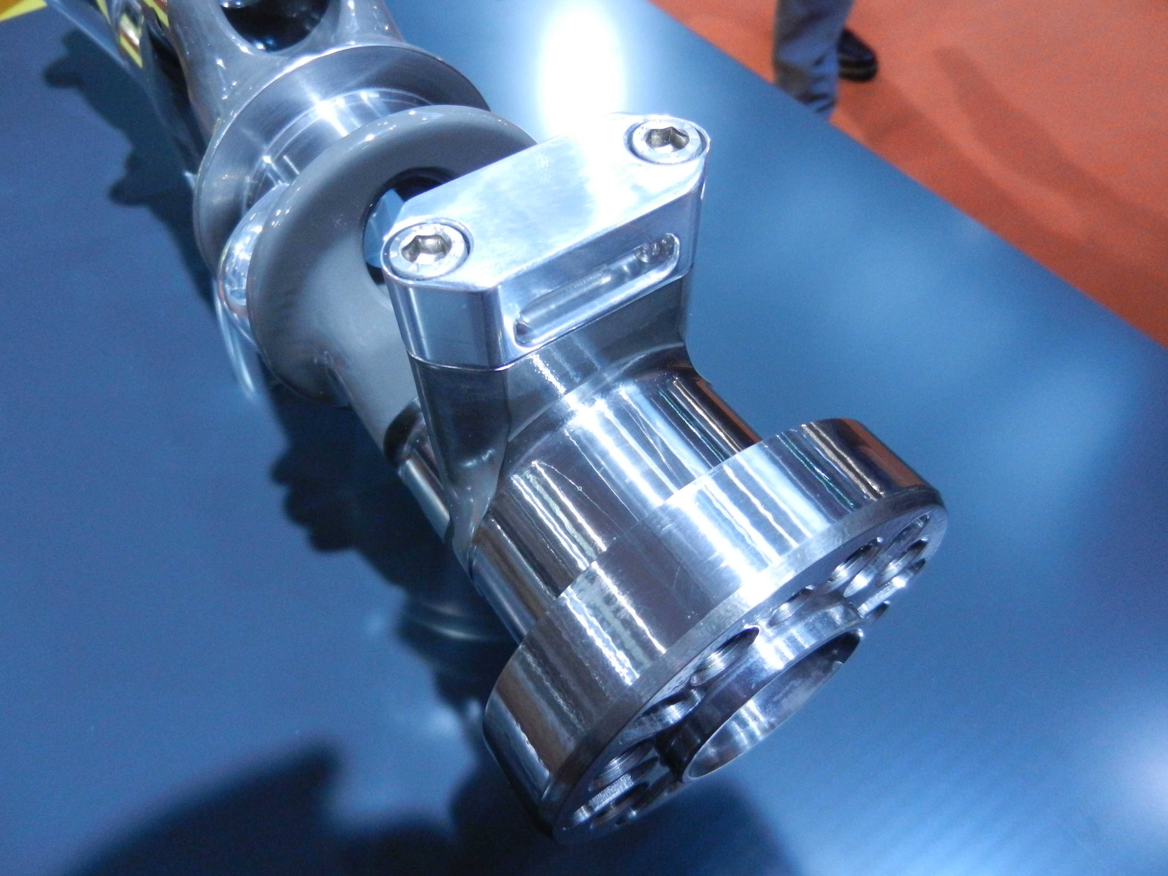 Fig. 1 - Clever machining facilitates clever design for an engine to go in an innovative car
Written by Wayne Ward
3592