The black art of machining composites
The pun in the heading above was too tempting to resist; in reality, however, Formula One engineering is all about knowledge, not magic. The challenge when exploring Formula One technologies is that this knowledge is closely guarded, particularly when it delivers a performance advantage.
To this end, carbon fibre reinforced polymer composites (CFRPs) have always had a certain mystique about them. This is due in part to the relative newness of the material (compared with the maturity of metals), the complexities of design and manufacturing and the high material and production costs. It is also something that some engineers are happy to encourage.
Composite knowledge has always been a valuable commodity in racing and is becoming highly desirable in many industries. Composites now have significant commercial value – they are ‘mainstream’ and are very fashionable.
This shift has been driven by the global quest for efficiency, and in particular the aerospace industry’s leap from aluminium to composite airliners. The need for larger volumes and lower costs are advancing composite development outside of Formula One and with perhaps even greater challenges to overcome. Machining is of prime significance, and the knowledge created in Formula One is finding its way out and being developed further.
The fundamental guide to machining composites in Formula One is simple – avoid if possible. This is a sound approach in racing for many reasons. First, you have to create a mould tool in which to laminate your component. This is generally an order of magnitude more expensive to produce than the part itself, so rather than machining features as an additional operation, the goal is to ‘mould in’ all the desired geometry.
Second, composite assemblies are a challenge. Joining metallic components has well established techniques, such as welding and bolted or riveted joints. With CFRPs though, welding is not possible and the anisotropic properties of the material can make mechanical joints unreliable without a proper understanding the composite’s characteristics. This has led to the development of bonding technologies where structural adhesives are used to combine two or more composite and metallic components.
This can produce joints where the adhesive bond line is actually stronger than the matrix of the composite itself, but its success and repeatability relies on meticulous preparation of the bonding surfaces, control of the bond line thickness and thorough execution of the bonding procedure. Ironically, bonding composite parts often required the machining of the joint surfaces as part of the process.
So Formula One engineers look to reduce the part count, and therefore the need for joints, by designing integrated composite structures. Not only does this remove the need for bonding and machining, it often saves weight, improves component stiffness, can optimise the load paths though the structure and can reduce cost and manufacturing time.
Inevitably though, the need for machining is always present as the Formula One car cannot be manufactured as a single CFRP component. The cars are highly adjustable, parts require replacing and ultimately composites are not always the material of choice for every component.
Most composite machining in Formula One is driven by the need for precision. Moulding cannot always deliver the accuracy required for ‘close tolerance’ mounting features, whereas machining can.
These mounting positions often require ‘hard points’ with homogenous properties. This is generally achieved by adding machined quasi-isotropic CFRP ‘stock block’ inserts that are either co-cured or cold bonded into the laminate and then post-machined.
Machining composites is just like machining any material; the trick is learning how to do it accurately and efficiently. It does however present some additional challenges over those encountered with metals. Below is a list of the major challenges that composites pose and some of the current solutions that have been demanded by Formula One and latterly other industries.
Dust: Aside from inexperience with composites, this is probably the biggest obstacle preventing a machine shop from offering CFRP machining services. The dust can accelerate machine tool (mill or lathe) wear, requiring increased servicing and maintenance, and is a challenge to clean, especially if the machine cuts other materials with the aid of coolant. This is best addressed with an extraction system.
Tool life: Composites are highly abrasive, which leads to rapid tool wear and frequent tool changes. The solution to this is to use polycrystalline diamond (PCD) cutters, which offer dramatically increased tool life over standard carbide cutters as well as improved surface finishes.
Surface finish: The best finish is achieved using PCD tools, as mentioned above. However, machining strategy, cutting speeds and feed rates, and depth of cut also influence the surface quality (as with metals). When surface milling a technique called Sturtz milling [Fig. 1] – where an end mill cutter is tilted (between 2° and 20°) replacing the more traditionally used ball nose tool – can offer improved surface finishes and higher material removal rates. It is also important that the strategy selected considers the heat generated whilst machining. If the surface temperature becomes too high damage can be caused to the polymer matrix as it will soften and depolymerises.
Delamination/splintering: These are the most common problems encountered when edge milling (profiling) CFRPs, and occur when the cutting forces damage the edge of the component as carbon fibres are broken out of the matrix [Figs. 2 and 3]. This can be countered by using a compression router end mill [Fig. 4], which is designed with both positive and negative helix angles simultaneously compressing the top and bottom edges of the part to reduce splintering.
Multiple materials/different properties: Another challenge with machining CFRCs is related to the very definition of the material – a composite. The composite can be constructed from a combination of carbon fibres with different properties (modulus and strength), different fibre types (glass, aramid, zylon) and/or metals such as titanium.
The different characteristics of each material affect the machining strategy and can result in a compromise. For example, when drilling composite-titanium stacks a phenomenon known as composite erosion can occur. This is the radial deterioration of the composite material exit surface caused by the evacuating metallic chips (also known as swarf) during drilling [Fig. 5]. A technique called micro-peck drilling can be used to reduce this erosion and minimise the burrs on the metallic exit surface. It works by applying periodic low-frequency axial motions during drilling to produce smaller chips, resulting in improved chip evacuation.
There is extensive ongoing r&d into composite technologies, including machining. Techniques and tools are evolving to meet the increasing demand and applications for these materials. Interestingly, as composite applications increase outside of Formula One the results of this development are more readily available, and as a consequence composite manufacturing is being perceived much more as science and much less a ‘black art’.
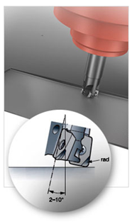
Fig. 1 - Sturtz Milling (Images courtesy of Sandvik Coromant)
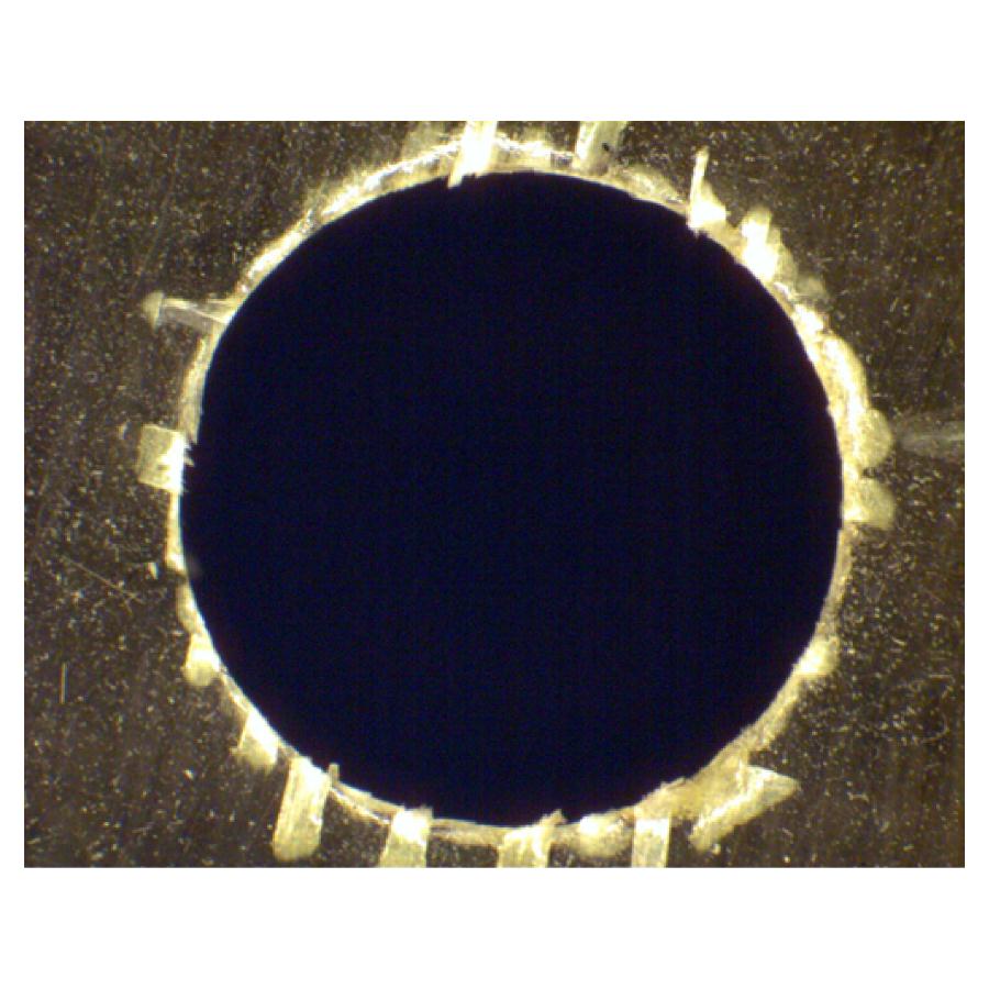 Fig. 2 - Delamination
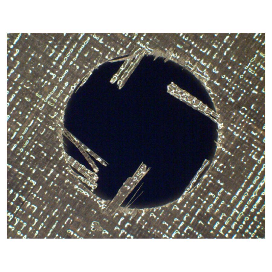 Fig. 3 - Splintering
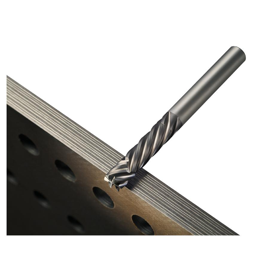 Fig. 4 - Compression router end mill
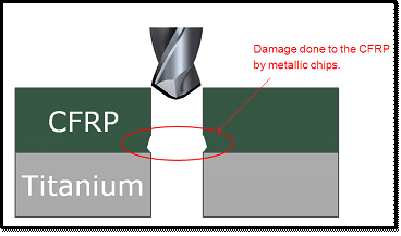
Fig. 5 - Composite erosion in a stack
Written by Dan Fleetcroft
5219