Combustion analysis
To even begin to understand the processes within the internal combustion engine, knowledge of the pressure in the combustion chamber relative to the crank angle position is surely an absolute prerequisite. Knowing how the combustion pressure as applied to the piston crown changes throughout the engine cycle can give an insight into fundamental gas dynamics, from which, for example, optimum engine efficiency can be established or the magnitude and nature of the loads inside the engine derived.
However, the techniques for determining such data, once solely the province of the research laboratory, are now widely available to the point where even the humblest of engine development establishments will routinely produce it on a regular and ongoing basis. Referred to simply as 'combustion analysis', the heart of the technology lies in the measurement of the precise pressure inside the combustion chamber at every 0.1 crank angle degree or so throughout the cycle. For this, and apart from an accurate crank angle encoder, pressure transducers capable of measuring accurately up to 300 bar have to be incorporated into the engine with the ability to withstand up to 500 C and have an output signal that varies little with temperature.
While many pressure measurement transducers still use strain gauge technologies, when high combustion loads are to be recorded at such demanding temperatures the only practical way is to use a piezoelectric sensor ,which at its core uses a single crystal measuring element. If a load or pressure is applied to this crystal, an electric charge proportional to the load is produced, which when amplified and converted to a 0-10 V dc output can be fed into any suitable data logger alongside the associated crank angle encoded position. The drawback to this electric charge is that it soon dissipates, so piezoelectric transducers, while excellent for transient pressure measurement, are not so useful if pressures are quasi-static.
The working element of the transducer uses a single quartz (silicon dioxide), gallium orthophosphate (GaPO4) or similar crystal, and will have been grown from scratch under carefully controlled conditions taking many months. Once of sufficient size (and since the orientation of the lattice is important to the properties of the sensor) the crystal ingot will be carefully X-rayed to determine the major axis and then carefully sliced into thin wafers. Depending on the crystal type, the result will be a compact transducer of perhaps no more than 4 mm in diameter at its base but with a pressure sensitivity of 2-12 pico Coulombs per Newton (pC/N) and which is reasonably insensitive to variations in temperature throughout its designed operating range (generally 0-500 C).
In the world of 'combustion analysis' such transducers invariably have to be small since space around the combustion chamber is invariably tight. Getting the transducer close to the chamber to obtain the best possible signal is therefore not easy. In some cases, and where access to the casting patterns is available, certain cylinder head cores may need to be 'rubbed' to produce just that little bit extra casting thickness. This is necessary to machine a suitable access point for the transducer and not have to pass through the cooling jacket. In other cases, for instance when modifying more standard cylinder head castings, this might not be possible and transducers have to be obtained that can 'bridge' these waterways, against the coolant at both the lower and upper ends. Since in my experience these are rarely successful in high-performance engines, other methods such as welding in special sleeves may have to be developed.
While not always as easy as many would have you believe, once combustion pressure data is available you wonder how you ever managed before without it.
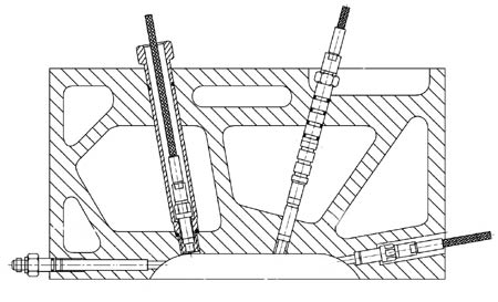
Fig. 1 - Transducer installation methods
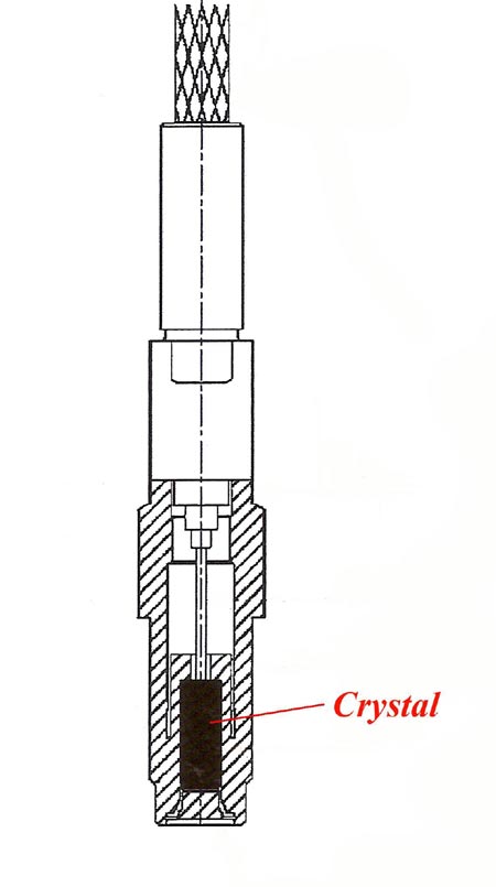
Fig. 2 - Typical transducer
Written by John Coxon
3479