Gearshift load cells
The world of race transmissions has changed substantially over the past 20 years or so. Although the geartrain cluster may fundamentally be the same, with only relatively small improvements to the gear teeth profile or material, the main developments would seem to be mostly around the gear change itself and the speed of gear change. And while developments to the gear cluster saves weight or improves reliability, those to the speed of gear change save time – arguably a far more precious commodity in motorsport.
In order to save time though, the actions with the change mechanism have to be synchronised, and the way to initiate this in a typical flat shift system is to use a gearshift load cell. Positioned in one of two places – either in the change link rod to the transmission or as part of the gear knob on top of the gear stick – the electrical output of the cell, triggered by the forces generated by the driver wishing to change gear, provides a signal to the engine ECU to initiate the sequence of events. Originally used in Indy or Touring cars when not using a paddle shift gear change, these load cell are now found in all sectors of motorsport where flat shift gear changes on sequential gear change systems are required.
When fitted in the change link to the transmission, the load cell is generally a simple strain gauge set-up that measures compressive or tensile loads in the rod. As part of a Wheatstone bridge circuit, and together with signal conditioning and amplification, the electrical output will be a simple, temperature-compensated 0.5-4.5 V linear output that can be fed directly to the relevant pin on the engine ECU. The linear output makes setting it up in the engine control software a simple matter, for once the upper and lower limits are selected, the ECU will initiate the ignition cut as soon as the correct level of force (as set in the software) is obtained in the rod.
In the other option – as part of the gear knob – the arrangement of strain gauges is slightly different, but the voltage output is much the same. Here the strain gauges will be so arranged to measure the bending moment in the gear stick, so they are bonded onto the stainless steel inner sleeve in a different orientation. In both types of load cell, to protect the gauges and offer a more aesthetic product, the whole assembly will be sealed into an outer casing made from aluminium alloy. Trailing out of the sensor will also be a fly lead typically 0.5 m long with three 26 AWG sleeved wires: supply, ground and output.
However, irrespective of which method you use, the minimum force necessary to unload the gear teeth and initiate the gear change will be different in the lower gears than that required at higher speed. The loading between the engaged gear teeth and the speed of the shafts all have an influence on the optimum performance. Where the engine management system allows, a rotary sensor attached to the barrel of the sequential change mechanism can be used to indicate the gear, and the minimum force required fine-tuned to each actual gear change. In this way the minimum time is lost for any and all gear changes.
These sensors may be small but they certainly ‘punch’ well above their weight when it comes to changing gear.
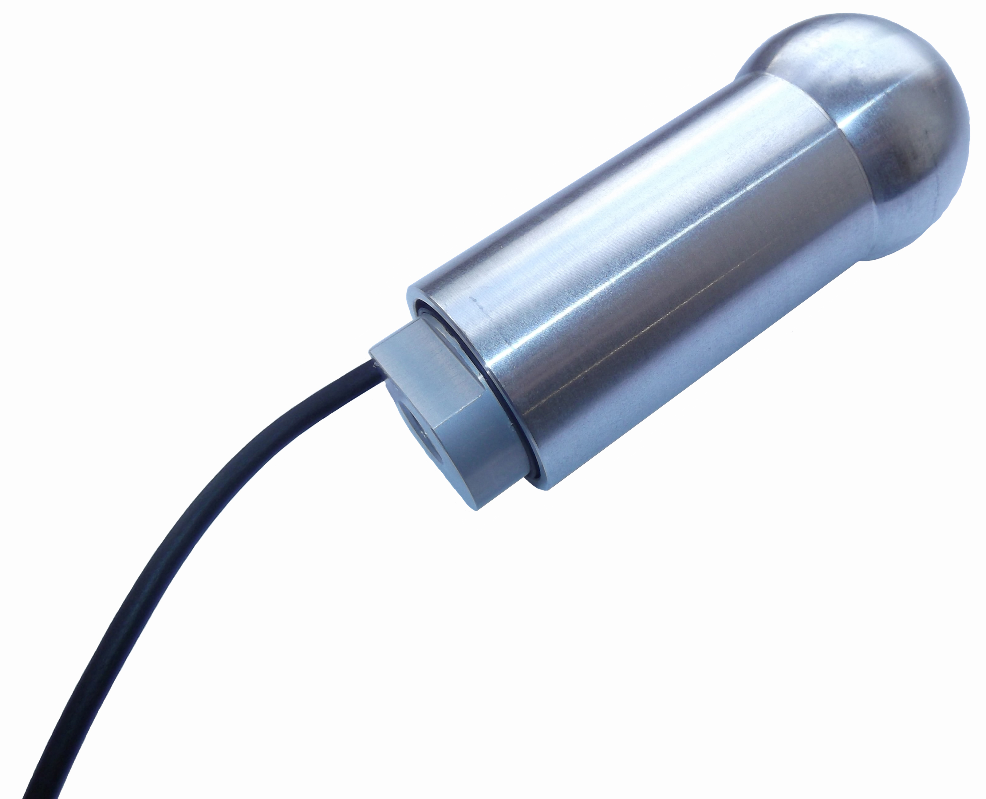 Fig. 1 - Gear lever load sensor (Courtesy of KA Sensors)
Written by John Coxon