Solder or crimp?
 Life is full of decisions, such as shall I wear the yellow or white shirt today, never thinking, of course, I have only one tie - pink! Or the classic one of betting all your money on red in a game of roulette, and the little ball ends up on the black. Sometimes, however, these decisions are taken away and life can be so much simpler. But deprived of choice, as an engineer I begin to wonder if there is a better way or if the accepted practice was just a convenience brought on by expediency with some other object or motive in mind?
One such decision to be made by anyone undertaking any form of vehicle wiring is whether to solder or crimp.
Let me start by saying that virtually without exception, the motorsport industry, the aviation industry, the automotive industry and even the marine industry all seem to adopt crimping as the norm. Safe and secure crimps produced using high-quality crimping tooling sometimes costing many hundreds of pounds and used by trained individuals to a set and closely monitored procedure can rarely be faulted. And with gauging technology to determine any wear in the tooling above an acceptable amount, it is perhaps easy to see why the industry has adopted these methods.
But ask any electronics engineer and they will readily admit that the highest quality of any electrical connection is best served using a soldered joint. After all, we still connect electronic components to a printed circuit board using solder, and if failures in these are now somewhere nearer one in 100,000 or greater, it surely can't be the actual fault of the solder. Or can it?

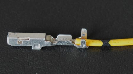
A typical electrical connection on a vehicle, aircraft or boat requires three things - low electrical resistance, good mechanical strength and protection against the environment. While low electrical resistance may seem to many to be the overwhelming necessity, in actuality the largest issue is likely to be one of mechanical strength. An electrical lead attached to any connector is in fact a cantilever, and like any cantilever it is therefore subject to all manner of vibration-induced bending moments. In a crimped connection, the central electrical connection will be crimped to the wire with a separate outer grip crimped to the protecting elastomer outer sheath. The former provides adequate electrical connectivity but the latter restrains the sheath.
In soldered joints the mechanical security of the joint is obtained by the 'wetting' action of the tin within the solder on the substrate beneath, but capillary action with the wire strands will draw the molten metal up away from the joint. So while we may have a perfect electrical connection, the hardened solder within the wire will create a weak point, and the wire will eventually break due to fatigue.

The application of heat, even if done so carefully, can also soften the outer sheath and may damage its properties, further impairing its flexibility. Using traditional tin-lead solders (37% lead, 63% tin) with a melting point of 183 C, soldering is difficult enough. Now that lead in solder is outlawed and a new lead-free product - tin-antimony or tin-copper, to name but two - will have to be used, this melting point will be higher, and the risk of damage to the protecting sheath therefore greater.
So it seems logical that crimping is the way to go.
And me? Well I have a copious supply of tin-lead solder and I like the apparent security of a properly soldered joint, despite the difficulties and the risk. Using crimped joints I apply just the smallest amount of solder on the first electrical crimp and use the second outer crimp for mechanical security, ensuring of course that all soldering fluxes are carefully removed afterwards. It's a bit of a 'belt-and-braces' or 'hedging my bets' approach, but it always seems to work for me. There again though, with my record in making decisions, what do I know?
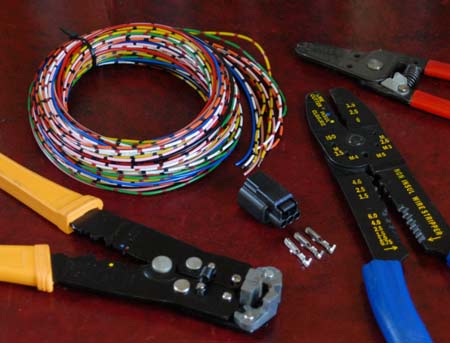
Fig. 1 - A selection of inexpensive crimping tools
Fig. 2 - Solder or crimp?
Written by John Coxon