Two into one does go
When I was a schoolboy, during mathematics lessons on the subject of ‘long division’ I always remember being told that two into one doesn’t go. The rules of mathematics were something to be followed without question, but these days of course I now know differently. Because when it comes to electronic sensors, particularly when weight or space is the concern or for safety-critical applications, then two into one certainly does go.
The most obvious example of this is when two differing properties of a substance are required at the same time, such as the pressure and temperature of the intake air in an engine where space might be limited. In this case an integrated circuit of, say, a piezo-resistive pressure-sensing element could be combined with a sensor of negative temperature coefficient – a material whose electrical resistance falls with temperature – to monitor the pressure and temperature of the incoming airflow. With the integration providing temperature compensation for the piezo-resistive device, we now have two highly responsive signals for the size of one, and convenient 0-5 V signals to input into the engine ECU. In addition to the reduced number of connectors and wiring needed, with no loss of signal accuracy, the combined unit could well be cheaper too.
While this may not be the world’s most exciting example, contrived to save only weight and perhaps a little money no doubt, a greater and more worthy application of the concept is in safety-critical components and particularly those involved with engine control.
Because of the much greater demands on their efficiency and refinement, modern engines are said to be ‘torque controlled’. To smooth out the fluctuating loads within the engine and deliver the required torque to the driving wheels, the driver’s accelerator pedal has to be connected to the engine throttle valve not by a mechanical link or bourdon cable but by an electrical wire passing the demand signal to the engine ECU. Such systems, now ubiquitous in all modern engines, therefore need a means of signalling the driver demand from the accelerator pedal, a means of opening the throttle plate (using an electric motor) and a means of measuring its position – all at the same time. And if any of the sensors were to fail and, say, the throttle was driven wide open when the driver wanted to brake, the results could be catastrophic!
To combat this eventuality, system designers include a degree of sensor redundancy into the system. Within the pedal or engine throttle sensors there will be two separate rotary potentiometer circuits, each providing a separate signal to the ECU. One circuit might for instance be supplying a 0-5 V (actually more like 0.5-4.5 V) signal while the other circuit might be supplying half this (voltage) but in the opposite sense. In other words, if the signal is increasing on one circuit as the throttle is opened then on the other, as well as being half its maximum, the voltage will fall as the throttle is opened. In this way the engine should always know where it is, and should the worst happen and a sensor fail then catastrophic failure will be totally avoided, with the engine stopping totally – or, more likely, going into ‘limp home’ mode.
Although during my childhood ‘two-into-one’ didn’t go, these days I for one am grateful that it now does.
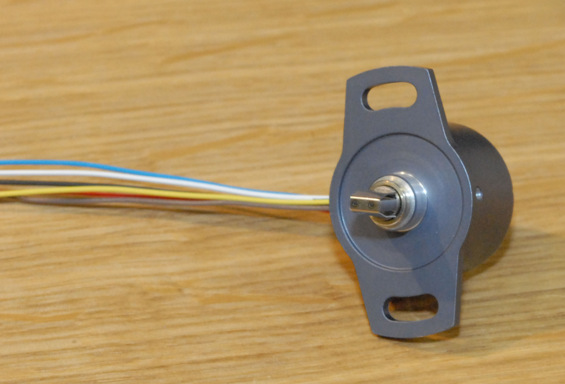 Fig. 1 - Duplex rotary throttle potentiometer
Written by John Coxon
3485