CFD for cylinder heads
 In my past three articles on heads-blocks, I took a closer look at cylinder head loading. The main focus has been on the thermal loads of the cylinder head and which parameters of its design are of most influence in preventing it from cracking due to the thermal loading - so-called 'thermo-mechanical fatigue'.
In my most recent article, a number of options were mentioned to reduce cylinder head flame-deck temperatures - achieving good flow conditions and velocity of the coolant through the cylinder head, transferring heat as quickly as possible from the heat source to the cooling medium and getting coolant as near as possible to the hot areas. In this article I would like to focus on the first point, coolant flow conditions and velocity, and provide information on the advantages and disadvantages of different cylinder head coolant flow concepts.
In general, one can distinguish between two basic coolant flow concepts. The first is longitudinal coolant flow, which can be described as a coolant flow that enters the cylinder head at one side of the engine and flows through the cylinder head to the last cylinder in a longitudinal direction along the engine block, where the coolant's exit is located. This means that the heat of the first cylinder will heat up the coolant before it enters the following cylinder.
The second is transverse coolant flow, also called parallel flow. Transverse is the opposite to longitudinal, and is where the coolant flow enters the cylinder head at the side, and where the return is oriented at the opposite side of the head. In this case, the flow direction is perpendicular to the longitudinal axis of the engine block. In other words, all cylinders will receive the same temperature coolant.
What are the major differences between both concepts when focusing on cooling performance? In the longitudinal concept, the coolant is fed to the cylinder head through an entrance at the front of the first cylinder - or at the rear of the last cylinder - where it will flow through all cylinders to the opposite side. The consequence is that, at every cylinder, heat is transferred to the coolant, leading to a heat-up per cylinder, which is not very pleasant for the last cylinder.
The parallel concept typically requires a coolant gallery, mostly integrated into the crankcase, from which coolant feeds per cylinder are designed towards the cylinder head. For maximum cooling, the entrance of the coolant is often located just between the exhaust valves, where the cooling efficiency on the exhaust valve bridge is highest. Looking from the top side of the cylinder head, the coolant has three ways to flow, through the other three valve bridges. The goal is to design the coolant jacket such that all valve bridges receive just the amount of flow in order to achieve sufficient cooling. This is where Computational Fluid Dynamics (CFD) analysis is an absolute must in order to predict the flow pattern.
For both concepts a difficult area to predict and influence flow is around the centre of each cylinder. Typically, a dome is located just in the middle for either the spark plug or the injector. For the spark plug, material is required for its thread, where for an injector either a sleeve is assembled to keep coolant away from the injector, or the injector is assembled in a casted geometry, both restricting the coolant flow significantly. Besides being a major obstruction, the coolant is also forced upwards at this centre dome, meaning that the coolant is not at the location where it needs to be - at the flame deck! These are typical issues that design engineers spend many hours and iterations on to get the flows and speeds just where they are required.
From a production (casting) perspective, the longitudinal concept is less complex. This is due to the fact that the casting of the cylinder head coolant jacket can exist out of a single solid structure, without having to keep the cylinders separated. With the parallel flow pattern, the cylinders need to be separated from each other, in order to force the flow from exhaust to intake side and prevent the coolant flowing to other cylinders, and reducing intensity.
And as with all other conceptual choices, these concepts can be combined. There are designs using an upper and lower coolant jacket, where the lower one is used to create a parallel flow pattern and the upper jacket as coolant transport gallery to a single coolant return gallery. This enables a more compact design as a true parallel flow concept, and is not much more difficult than the longitudinal coolant concept.
Nevertheless, it will not be difficult to understand that purpose designed high-performance race engines will be based on the parallel or transverse cooling concept, making it possible to achieve the highest cooling capacity by individual adaptations to the coolant flow per cylinder.
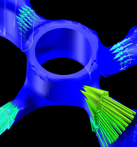
Fig. 1 - CFD image of cylinder head coolant flow
Written by Dieter van der Put
4762