Cylinder Heads / Blocks
 The process of engineering design is very much a compromise and sometimes, even with modern computerised techniques, several iterations may be required before the final, optimised product evolves. The design of a modern cylinder head can be a perfect example of this. Although four valves per cylinder with a central spark plug is ubiquitous in gasoline engines, as the included angle of the intake and exhaust valves becomes smaller, the architecture of the valve train and space for the fasteners to assemble it all becomes much more critical. This is especially the case when direct acting mechanical buckets (DAMB) are used.
In some designs, especially those with compact combustion chambers, the cam motion is often transmitted to the valves via finger followers. This has the double advantage of reducing the overall height of the cylinder head and removes the restrictions of lift on a given tappet diameter in a direct acting arrangement. And although each design has its difficulties, this is often the preferred route when using such narrow valve angles. However, for ease of manufacture (high quality mechanical tappets can be readily purchased ‘off the shelf’) and therefore maximum reliability, many manufacturers of endurance engines prefer to stick to the tried and tested technology of DAMB. But as the valves become more upright the space available becomes less and more compromises need to be made.
That landmark design in racing engines, the original Cosworth DFV surmounted the issue by introducing a separate cam carrier as part of the ‘sandwich’ construction of the cylinder head. Consisting of a one piece aluminium alloy casting which held both the tappets and the camshaft, this was bolted to the main structure of the cylinder head by long studs which also served to retain the bearing caps and down the two middle rows at least, the shallow cam cover.
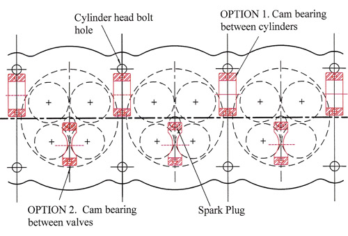
But such complication is not to be accepted in the volume engine business. Separate cam carriers and associated fixings mean added cost, while long studs can mean variable clamping loads. At the same time additional joints can provide a source of potential oil leaks all of which are undesirable and so the industry did what it always does in such circumstances – it simply removed the cam carrier from the Bill of Materials designing all future cylinder heads with integral carriers. However the introduction of the integral cam carrier further complicates the design. Since access from above is still required for the cylinder head fasteners and with fixed cylinder head bolt positions and a camshaft centre line dictated by the valve positions, the problem of the location of the cam bearing fixings can be a trial. In the end the traditional approach of positioning the cam bearings above and between the cylinders had to be rejected. The proximity to the cylinder head bolt positions effectively rules this out. The final, albeit compromised, design was to have the cam bearing not between cylinders but between the cams of each cylinder. Although restricted by the diameter of the tappets, which in turn limits the cam profile velocity, this would seem to offer the stiffest solution. Once fully proven by the volume manufacturers, the smaller race engine suppliers followed suit.
And the cam carrier? R.I.P. - Rest in Peace.
Written by John Coxon.
4266