Deformed head
 It's an obvious thing to say, perhaps, but while an engine has to contain lots of moving components in order to function properly, it also contains many parts that are not intended to move at all. For example, cylinder heads and crankcases are not intended to move, but they are still in motion. In this article, 'motion' means that by introducing loads to the structure of these components, continuous deformation will take place, depending on the magnitude of that loading.
Where the external loads are strictly mechanical, these deformations typically remain in the elastic area, meaning that the deformation will disappear when the external load is removed. These kinds of deformations are so-called linear deformations. As explained in earlier RET-Monitor articles, for example here, plastic deformations also occur in cylinder heads, mainly as a result of heat loading.
When mechanical loading (combustion, assembly) is combined with thermal loading (heating up/cooling down), things get more complicated. But there is some pretty straightforward analysis on the relation between the deformation of the cylinder head (due to heat) and cylinder head design, in this case valve pattern orientation.
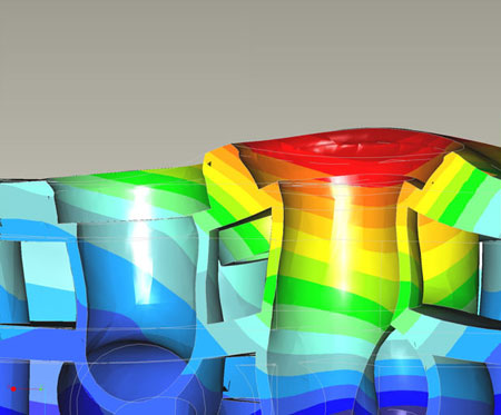
The starting point of this analysis is the fact that the exhaust valve area is the most heat-influenced zone, and is more or less shaped as an ellipse around both exhaust valves. The result of the difference in heat loading between intake and exhaust is that the flame deck on the exhaust side will deform into the combustion chamber significantly more than the cooler intake side. When considering a straightforward four-valve DOHC race cylinder head with a parallel valve pattern, this deformation will be quite symmetric. Most of us engineers are symmetrically focused, and therefore we will find rather easy the required design solutions in order to withstand these loads.
But, considering that some race engines also still use other valve patterns, such as slightly rotated, diamond-like valve orientation or even the older two- or three-valve heads with asymmetrical valve orientation, the deformations start to look far more complex and not so straightforward.
Some years ago I had two students doing their practical assignment under my supervision. I gave them the task of investigating the deformation effects of heat loading on several cylinder head concepts (existing competitor cylinder heads were taken as input), using simple-concept CAD and CAE modelling. A couple of design variables were defined, where valve pattern orientation was the primary one. Heat loading was kept constant to get clear comparison.
Something perhaps already known to some RET-Monitor readers, but which was an eye-opener at the time for us, was the simple fact that either a zero or 90° valve pattern was pretty easy to control from a deformation point of view, but valve orientations in between these values led to significant asymmetrical behaviour when looking at the area where the exhaust ports connect to the cylinder head and the main head geometries.
The exhaust valve area deformations are transferred through the port structures to the upper regions in the cylinder head, leading to significant stress levels at the locations where these connect to the main structure or port-to-port connections. Making geometry modifications to several areas of the cylinder head structure - such as flame deck thickness, profile, port geometry, port wall thickness, coolant jacket shape and so on - provided a conceptual understanding of creating the geometry in such a way that the stresses could be absorbed in an homogeneous area, in order to prevent stress concentrations, possibly leading to cracks.
As mentioned above, the goal has been to provide some basic insight into the different aspects of cylinder head loading, and the consequences. Where the thermo-mechanical fatigue was described and discussed in earlier articles on the Heads-Blocks keyword, this article has focused more on the additional mechanical loading and load paths due to thermal deformation of the flame deck. When investigating these areas using rather simple conceptual designs, a basic engineering feel and experience can be developed that helps in understanding the complex behaviour of cylinder heads.
Engineering cylinder heads in these times requires the use of high-end CAD and CAE packages, which cannot be overlooked any more - certainly when designing these components on the limit between loading and mass. But engineering knowledge and conceptual understanding of cylinder head behaviour is required before these tools will deliver added value to the design.
Fig. 1 - Deformation of the cylinder head
Written by Dieter van der Put
3158