Liner flange design
In this article I will take a closer look at the specifics of the liner flange design and what one should take into consideration, with the goal of trying not to crack it.
In principle, cylinder liner design does not look too difficult. It is more or less a machined cylindrical component, often with a flange somewhere of somewhat bigger diameter to keep the liner at its correct height. But on closer inspection there are a lot of things that might lead to distortions of either the liner itself or the surrounding crankcase structure. Most of the time when this occurs, an engine will be totally lost, so the liner is a critical component in the engine.
Starting with its function, a cylinder liner guides the piston in its path going up and down, and also plays a role as part of the combustion chamber, keeping combustion inside and coolant and oil outside. Seems rather simple, doesn’t it?
In doing so, however, the liner will interact with a number of other components, each of which has specific interface requirements. Let us start with the obvious: sealing the combustion chamber between the cylinder head and the crankcase. In this particular example the liner, a top-stop type, needs to seal at two locations – the first between the liner’s upper side and the cylinder head, and the second between liner flange and crankcase. And where the first, almost without exception, uses a gasket between both parts, the latter almost never does.
In general, the liner flange and head gasket are clamped together between cylinder head and crankcase by the cylinder head bolts. These bolts introduce significant forces , which can be influenced by following design parameters:
- Number of bolts. The more bolts that can be used in the design, the lower the load per bolt will act on the liner, leading to fewer distortions over the circumference of the liner flange.
- Flange protrusion. The more the liner flange protrudes above the crankcase top surface, the more bending each cylinder of the cylinder head suffers from, leading to high local loads on cylinder head and liner.
- The diameter on which the head gasket seals to the liner top surface. This is one of the most critical design parameters. Most head gaskets have a region called the compression diameter, where the gasket has its sealing function; often this is a specific shape in the gasket. When this diameter is equal or smaller than the smallest balcony diameter of the liner flange, a bending force will occur on the radius below the flange – one of the most sensitive areas of the liner. Since the compression diameter is kept as small as possible, because combustion pressure acting on this diameter might otherwise be too high, there will always be a minimal difference in diameter.
- The radius below the liner flange. Where a large radius is definitely favoured, this will automatically lead to a larger flange diameter, since the mating face between liner and crankcase needs to be of a certain minimal area, keeping contact pressures within their mechanical limits. Smaller radii at the flange area could lead to liner cracks just below the flange, in exactly that same radius.
- Flange radius surface treatment. A surface treatment is often added to the radius of the flange. With shot-peening, relatively small objects – often ball shapes – are impacted on the surface, where they cause plastic deformation of the surface, albeit minimally, leading to compression stresses in the base material. This in itself increases the basic strength of the material locally, leading to improved mechanical properties. Caution should be exercised over the peening materials and pressures, however, since overdoing it might also lead to earlier failure of the component.
All in all, liner design has a lot of simple and somewhat less simple areas of interest. Some areas are straightforward, while others require more focus and depth of knowledge. Since the liner, as a separate part in the engine, is still regularly used, engineers will continue to try to improve them, making them lighter but without reducing their mechanical properties too much.
This is what makes engine design so interesting – a rather simple component with a lot of very interesting and critical engineering areas.

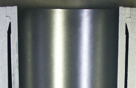
Fig. 1 - Section view of a liner design with the significant areas of interest
Written by Dieter van der Put