Setting targets?
 An issue often not immediately considered when discussing an engine component such as a cylinder head or engine block, or any cast or forged part of them, is the way the machined features are positioned into the rough part. These features need to be positioned - or 'targeted' - correctly onto the casting, in order to get to a fully functioning component as the end product. So what are the important points during this initial machining, which will create the basis for all other machining features? It seems simple, but in reality this is one of the most important and critical steps of the machining process. A small error during this machining operation can make a component useless.
Why is it so important and difficult to position the machining features correctly to the casting or forging? There are a number of reasons, but the main one is to be able to produce a part that has an homogeneous wall thicknesses throughout, without the risk of machining through the component's walls.
Every part has certain tolerances, within which the part can be produced - no part is ideal. Overall tolerances depend very much on the production process. For example, a part that is machined from billet has only the machining tolerances to take into account. These can be maintained very tightly by expert machinists on modern machining equipment. But when the same part is machined from a casting, the situation is more complicated. Considering that the casting process is a very complex one, in which molten material is poured into a mould made from sand, one can imagine that the tolerances achievable will be different from those of the billet, although the demand on the end product is the same.
The cast part itself already has certain tolerances of shape, within which the machining features need to 'fit'. The overall shape of the casting depends, among other things, on how the patterns are positioned, how much the cast part deforms and shrinks during cooling down. Sometimes the component even deforms during cooling down due to its internal stresses; see the latest article on the Heads-Blocks keyword.
Starting from the rough casting, the machining process needs to be initiated from certain reference points, called targeting points, which are often a number of specific cast shapes integrated into the casting. With these points the casting can be positioned for all six degrees of freedom. Typically the internal geometry - the crankshaft main bore and cylinder bores - is of most importance to the function of the end component. Because of this, the reference points are often located within these geometries.
Based on the deformations of the cast part, the crankshaft bore is often taken from the second and last-but-one main bearings. The outermost main bearings tend to show slightly higher tolerances in outward bending than the inner ones; this will centre the crankshaft bore. Taking the longitudinal references (sides) of these outermost main bearings will position the length of the part. After this, the cylinder centre lines are measured and taken as reference. Their positions will be averaged to achieve the full fixing of the casting.
When there's a smaller batch of cast parts to be machined, other geometries are counter-measured against this fixing position, creating a final chance to make slight modifications to achieve the best overall fit.
In this way the machining features will be best positioned into the casting, but it's only when taking a closer look at these reference points that one will start to realise their importance. For example, a pattern in the traditional sense - in comparison to pattern-less parts, created by laser sintered cores, for example - requires the several cores to be deformed out of the pattern. This means that, depending on the split line of the pattern, some of the reference points might not be exactly 'flat' but have be slightly tapered. And although these influences are mostly minor, these need to be taken into account, especially when considering the minimal wall thicknesses used in today's high-performance engines. Every extra millimetre of material in the overall wall thickness needed to compensate for these tolerances will add mass to the component.
This is exactly why the machining, both pre-machining as well as finishing, needs to be done by specialised machinists in well equipped machine shops. From the outside it often seems rather simple, but when exploring the production processes in detail, one will find out that the devil is often in the finest detail.
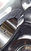
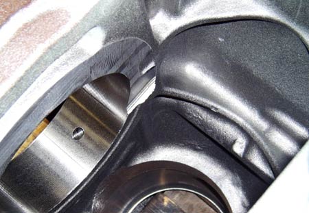
Fig. 1 - Offset machining due to reference point casting error
Written by Dieter van der Put
2981