Structure is good?
When I started my first job as a design engineer I was given the task of engineering a crankcase, so the first thing I did was try to understand how a block was what it was. I studied the crankcases of rival engines, as well as earlier versions of ours, and tried to figure out why engineers did what they did and how they came to their decisions.
To be honest it took me a lot of time before I had any insights into crankcase design. The main reason was the fact that every design feature in a crankcase has multiple reasons for being the way it is – in fact, engineering a block is rather uncomplicated, as long as you know where to start. And of course you need a group of enthusiastic people working with you on all the different aspects, such as casting, machining and so on.
This article will look at how a structural approach can lead to a block structure required for the specific application intended for the engine. Typically the bore and stroke of an engine, as well as the type of engine (inline engine, vee engine and so on) is already known when the task begins, so for this article let’s assume it is.
The engineer will start with the CAD system by feeding the basic shapes into the computer, mostly related to the crankshaft axis and the cylinder centre lines. After this the cylinder distance will need to be chosen, in order to determine overall block length. Typically the major factor is the type of cylinder cooling – depending on casting wall thickness and/or cylinder wall thickness, the minimum distance can be chosen.
The only real major issue left is how the drive from crankshaft to camshaft is chosen. For high-speed or highly loaded engines, the use of a gear train is most common, and the gear width will be determined according to loading. Adding all these dimensions together determines the overall block length. The height of the block, measured from crankshaft centre line as the reference, depends only on stroke, con rod length and compression height of the piston. These values together determine the top deck of the engine; for vee engines the slant height also needs to be put into the equation.
Another major decision issue is the way the various loads are transferred through the engine structure. An example is the number of main bearing and cylinder head bolts, their locations and how they are connected. Drawing lines between these main engine bolts (from main bearing bolt to corresponding cylinder head bolt) and one can see how the structure is designed into the engine. Typically one would see thicker portions (cylindrical cross-section) between both bolt types – the so-called main bearing wall structure.
At this very moment the crankcase can be considered complete from a conceptual point of view. Rather simple isn’t it?
This reflects the engine as it functions on its own, however, not within the integrated design of it and the vehicle. In most passenger car applications the engine is mounted using mounts in the chassis, decoupling it in order to avoid vibrations for the driver, thereby increasing comfort. In the high-performance world though comfort is less of an issue, and often the engine is mounted as a structural part of the vehicle. Integration of functions leads to less overall mass, which is the goal.
When thinking about engine design and how these mechanical loads can be engineered for, taking a good look will reveal how the design has to account for these loads and what the load paths are into the crankcase. Often ribs or other strengthened areas can be seen where the pick-up points to the chassis are located. The engine block itself and its standard wall thickness are normally sufficient to withstand these structural loads coming out of the vehicle.
By the way, the total amount of crankcase area where really minimal wall thickness can be achieved is not very high. The high degree of integrated functionality (pump housings, support structures and so on) means many areas have thicker walls; only around the coolant jackets can some areas be found where the wall thickness is minimal.
So the engine structure is not really anything more than a structurally designed engine, and taking the logical steps in the correct order will automatically lead to the correct structure. Therefore, designing an engine block is not too difficult. One might ask: what is the most difficult design then? The answer is, all the easy stuff like pipes, lines and so on. Where a block gets priority, it is these smaller items that are typically not paid structural attention.
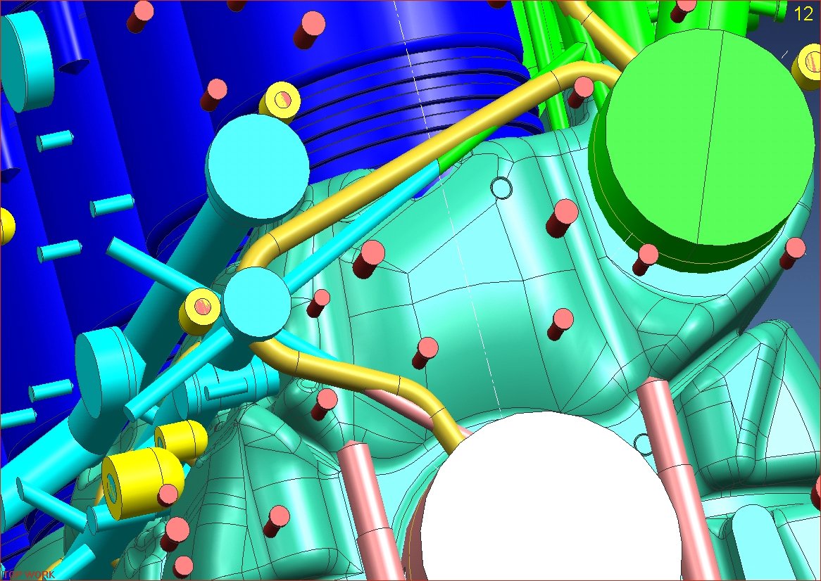 Fig. 1 - Overview of the structural features of an engine block/crankcase
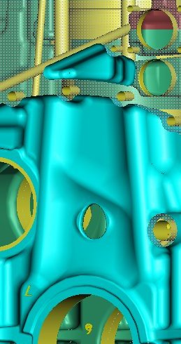
Fig. 2 - View of the main bearing wall and structure between main bearing and cylinder head bolts
Written by Dieter van der Put
3484