The Boring Detail
 Last time we looked at ways of producing high-quality cylinder bores. Needless to say, the thinking and methods used might seem extreme to some or insufficient to others. In all this, however, we must always remember that it is not the shape or degree of roundness of the bore that is necessarily important but the degree to which the piston can conform and seal the combustion gases that is perhaps more critical. We can make the bore as circular in cross-section as possible but unless the piston rings used can conform to that shape, little will be gained.
Before we go on to talk about shape it is perhaps useful to look at it from a theoretical perspective. Students of metrology will be familiar with the terms roundness and cylindricity and, along with that of the diameter, these describe the geometrical condition of any cylinder bore. A highly magnified trace of the surface through a section of the bore, and at right angles to its axis, reveals that what might look perfectly round to the casual eye is in fact composed of a number of peaks and troughs of varying size and undulation.
If we accept that the mean radius of this is denoted by the symbol R0 then mathematically either dynamically or statically, the actual surface radius Ra, can be given by the expression:
Ra = R0 + where is the polar angle, k is the order and A and are constants.
The mathematically fluent among you will recognise the above as a Fourier series where the 'out-of-roundness' term, is the sum of all the Acos(k( +?)) parts from k = 1, 2, 3 and so on up to the value of integer n.
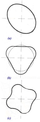
When k = 1 the bore shape is perfectly round. When k = 2 this becomes oval (picture (a) in the graphic). At k = 3 the figure moves towards a tri-lobe shape reminiscent of a cloverleaf (see picture (b)), while when k = 4 four lobes are now present (picture (c))
In theory, as n increases and all these increments are added together, the resultant shape (using the appropriate constants in each term) will describe precisely any cylinder bore you care to think of. In practice, however, although some experts suggest a limit of 5 or even 6, the more usual approach is to have a cut-off around k = 4.
At this point you might think these shapes are all very nice and produce pretty pictures. But when it comes to an understanding of them, each has a special significance.
When k = 2, for instance, referred to as second order, the ovality of the cylinder has much to do with the point at which the piston ring is touching the bore as it travels up and down. This reflects issues such as the thickness of the liner and how it is located (top, bottom or pressed fit).
When k = 3 (third order), excessive 'lobing' of the bore is a function of the imperfections as a result of the boring method and the equipment used. And when k = 4, experts tell us that shapes of this nature are caused by tensions in the cylinder block caused by fasteners and the like.
Thus when boring any block/liner, the representative loads caused by cylinder head studs or any other bolts need to be present. As a very minimum the main bearings should be torqued to the appropriate value while a boring plate of representative stiffness needs to be fastened to the top face.
So while bores can be measured with two- or three-point micrometers, to understand so much more requires a special machine called an incometer and some computer software. But we'll look at those at a future date.
Fig. 1 - Elements of the Fourier series representing a cylinder bore
Written by John Coxon
3060