The gap in between
 If you were to look inside the brain of any true engineer, you will find the phrase: "Make it smaller, cheaper and better". Smaller invariably means lighter, cheaper satisfies the bean-counters among us while better is the goal we often set ourselves, the one that plays to our ego and sense of pride, and the one we tend to judge ourselves by. So while designers are always producing engines to the smallest size, at some point someone in the future will always want to extract even more power.
The statement: "There ain't no substitute for cubic inches" is as true today as ever, so when it comes to extracting more performance the first call is often to increase the size of the bore. Unfortunately, since few of us ever get to design an engine from the proverbial 'clean sheet of paper', the inter-cylinder spacings have invariably been decided for us. Torn between a rock and a hard place, enlarged bores on a fixed-bore spacing means only one thing - a narrower 'bridge' area and the prospect of bore distortion, scuffed pistons and engine failure caused by inadequate cooling. Cooling is the key but the options are limited depending primarily on the original liner installation - either wet, when the liner is replaceable and in contact with the cooling water, or dry, when it is not.
During the combustion phase of a reciprocating engine, the part of the cycle that generates the greatest heat release is the mid-stage of combustion when the piston is towards the top of the cylinder bore. Depending on many factors, the heat release will peak at 20-30º after TDC, with 90% of the combustion having taken place by, say, 40-50º after TDC. As the piston moves down the bore the gas expands and cools, so the critical part of any cylinder liner as far as cooling is concerned is therefore towards the top 30%.
For a wet liner construction based on cooling concerns alone, a mid-supported liner with the upper face clamped against the cylinder head would appear to be the best approach. In such an application a cooling water jacket thickness of less than 1 mm in the zone where two spun-SG iron liners come together has been proved to be more than adequate in the past. The downside to this approach is that while supported at the mid-point and clamped against the cylinder head only at the top, the tops are effectively free to move and present potential cylinder head sealing issues. The alternative to the mid-supported wet liner is that of the top-supported version which, although having poorer cooling, produces a much robust surface for sealing and minimal distortion.
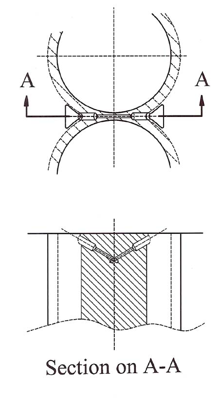
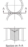
For dry liners and blocks using plated parent metal bores, the lack of cooling in the zone between the bores will be a major issue as those bores become larger. In a cast-iron block I once recorded temperatures in excess of 360 C at the top of this inter-bore region, so some form of cooling is normally an absolute must. In the end the only practical solution was to drill a series of holes of progressively smaller diameter to pass through the siamesed region and ensure that a pressure difference across the block would ensure the coolant would flow through it. With only what must be a very small flow of coolant, temperatures dropped substantially.
Easy to do? Certainly not, for the long drill bits used readily wandered during the process and the angle necessary to avoid the drill chuck hitting the face of the block was quite steep. But after two or more scrapped blocks (actually I forget how many) the modification was eventually completed.
Smaller than it otherwise would have had to be? Yes. Better? You bet!! And cheaper? Well, two out of three isn't bad.
Fig. 1 - Cooling the siamesed block
Written by John Coxon
2923