Valve seats, cool
 This is a follow-up to my earlier articles on cylinder head loading. Earlier, I described what is known as one of the most critical failure modes, Thermo Mechanical Fatigue, or TMF. In those articles the three main load cases were mentioned - assembly loads, (peak) firing pressure load and thermal load. For thermal load, further insight was given into the design of the cylinder head cooling jacket. The conclusion was that the jacket is mainly derived from the rest of the structural design, for example cylinder head bolt locations, inlet and exhaust ports and valve guides and seats.
On one of these items, the valve seat area, will be the focus of this article, and not so much the valve seat ring as a component, but as it is installed in the cylinder head and the relation to the cooling of the firing deck.
Assuming a certain experience and familiarity with valve seat assembly, readers will be aware that valve seats rely on a certain level of press-fit in order not to fall out of the cylinder head when the engine is running. Depending on the material of seat ring and cylinder head, a certain oversize of the rings is determined.
To be able to withstand the stresses introduced by the pressed-in seat rings, the cylinder head is designed such that a certain wall thickness is available around the valve seat. Where the valve seats are closest to each other, these walls will 'grow' together. Logic says that coolant cannot be in the same place as material, which means that at these locations the coolant will cool the flame deck less effectively.
In a previous article, I noted that the areas between the valves/valve seats, the so-called valve bridges, are highly sensitive to TMF. Because TMF depends heavily on the temperature delta between cold (engine off) and hot (engine full load), where the 'cold' situation cannot really be influenced, development should focus on reducing the valve bridge material temperatures as much as possible.
There are several options to reduce temperatures, but in general this means:
" Achieving good flow conditions and speeds of the coolant through the cylinder head
" Transferring heat as quickly as possible from the heat source to the cooling medium
" Getting coolant as near as possible to the hot areas.
The first point will be discussed in a later article. The second depends mainly on material choice, where aluminium, with its thermal conductivity value of around 250 W/mK, will remain the material of choice. The third point is the topic of interest here, and contradicts the situation described above concerning the material between the valve seat rings.
A typical high-performance, four-valve cylinder head has a maximum area of intake valves for improved breathing, leading to seat rings nearly touching each other. In this case, the only way to get coolant as close as possible to the flame deck is to lower the height of the seat rings to the minimum, while still achieving sufficient press-fit. It is in this area of the cylinder head design where development effort and simulation techniques are used to their utmost to achieve the best compromise between port size, design robustness and cooling.
In race engines where valve diameters are restricted, other possible improvements could be achieved by designing the coolant jacket in between the valve seats, as far as the casting tolerance and accuracy of pattern making allows.
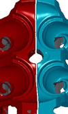
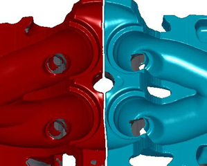
The image here shows a scanned image of a cylinder head (exhaust ports in blue) with the coolant jacket in between the valve seats. On the opposite side (intake in red), clearly there is no room to design in a coolant jacket. Given the thermal loading profile of the fire deck, the significance of coolant on the exhaust side is apparent.
One other interesting 'solution' needs to be mentioned, albeit only to illustrate the drive towards cooling of hot areas. Down the years, several designs have seen daylight - some even patented - which allowed for direct cooling of the valve seats. The general idea was to design the valve seat pocket in such a manner that openings were created, either by clever casting or machining, where coolant could directly reach the seat ring. Without having personal experience of these types of designs, most probably the design/manufacturing complexity and lack of stability of the seat ring area explain why these developments have not become common practice.
Fig. 1 - Scanned image of cylinder head design
Written by Dieter van der Put
3639