Fasteners: Back to Basics - Part 4
 Last month, we looked at some basic calculations regarding cyclic loading of fasteners. We must apologise for the recurring errors in printing symbols. The questions marks last month should have been ‘delta’ symbols. For example strain was given as:
e = ?L/L
This month we shall look at the calculation of joint stiffness, and the good news is that the methods and the basic calculations are the same. The combination of stiffness of different members is dealt with in exactly the same way. Where last month the calculation was dealing with different stiffness sections of the same stud or bolt, owing to changes in geometry, the individual calculated stiffnesses this month are for the individual components making up the joint itself.
To recap:
1/kt = (1/k1) + (1/k2) + (1/k3) + …..
where:
kt is the total joint stiffness
k1, k2 etc are the stiffnesses of the individual joint members.
For instance in a joint where two plates are clamped between two washers by a bolt, we would calculate the stiffness of the individual clamped members (two plates and two washers) and then calculate the stiffness as a whole using the above calculation.
Of course, if the geometry of each part is complicated, we can further subdivide this and treat it in the same way before using this stiffness in the overall stiffness calculation.
In calculating the stiffness of a bar in tension we assume that the whole of the cross-section is under stress and over the whole of the length. This is pretty much true. But what about a deep plate or some other geometry where the clamped area does not cover the whole of the cross section perpendicular to the fastener axis? How much of it do we include?
The theory is that the load spreads out from underneath the head of the fastener (or washer) at a given angle, and that the clamped material is therefore a truncated right cone (or frustum) with a simple hole in the middle. This is where the maths becomes more complicated / boring, so we shall just go straight to the solution.
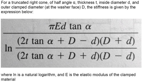
So, for a symmetrical joint, i.e. with plates of equal thickness clamped by washers of the same diameter, there is a truncated cone in the upper plate, and a mirror image of this in the lower part with their junction at the interface between the two plates. The diagram below shows the upper part of such a joint:
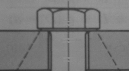
In joints which don’t display symmetry, the junction between the two cones will not be at the junction of the two plates, but this shouldn’t present a problem. The problem is still quite simple if the two plates are of the same elastic modulus. If they don’t have the same modulus, one of the cones will have to be split into two individual cones, each having its stiffness calculated using the above formula. Joints not displaying symmetry may have different thickness clamped members or perhaps it is a joint held together with a stud threaded into one of the clamped members, as per the diagram below:
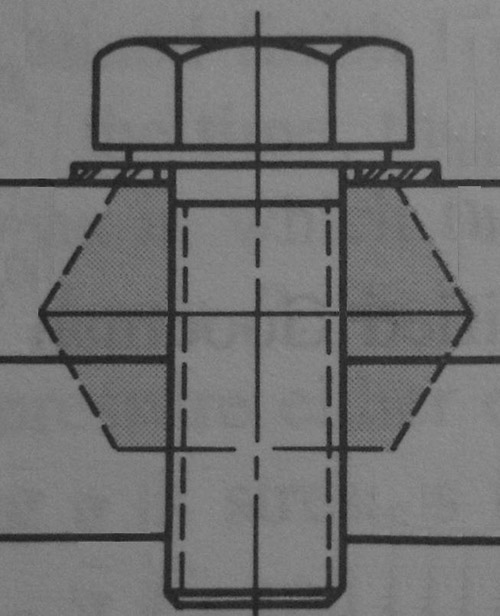
Where a stud is used, joints are often calculated using half of the engaged thread length being used to define the lower surface of the cone, but this depends on the geometry of the joint, and to some extent the length and quality of thread engagement. Reference books point to the fact that, beyond the first few engaged threads, little or no load is carried by the other threads unless special measures are taken.
Written by Wayne Ward.