The mechanical fuel pump
In the modern electronic world it is sometimes hard to believe that fuel injection systems in the higher echelons of motorsport, even as recently as the early 1980s, were totally mechanical in nature. One such system that is still in regular use every weekend in historic events is the Lucas mechanical system.
Still recognised as one of the most sophisticated yet easy to use fuelling systems of its time, and widely regarded as the most significant of its kind in Formula One history, the arrangement uses a moving shuttle to meter the fuel to individual cylinders. The shuttle operates between a fixed stop and a moveable stop to meter the flow and, using a rotor geared to half engine speed spinning around the metering sleeve, times the delivery according to angle of the transfer ports.
With a constant fuel pressure of up to 150 psi, the function of the injector is therefore solely to atomise the fuel rather than meter it. Fuel delivery at the normal wide-open throttle use of race engines is therefore proportional to engine speed, and is hence only an approximate (but perfectly satisfactory) estimation of the fuelling requirement. More than this, however, the system has a method of altering part-throttle fuelling using a 3D cam profile mechanically linked directly to the throttle.
Crude by 21st century standards, certainly, but the system was popular with engine builders simply because engine fuelling characteristics could be changed very easily with only limited test bed running. Nevertheless, since fuelling was timed to inject just at the optimum time, losses through fuel disappearing past the exhaust valve were minimised, producing surprisingly good fuel economy.
But all this required two fuel pumps, the first an electric one to prime the system and, once the engine was started, a second to keep the engine running. Mechanical in nature, this second fuel pump was a simple positive-flow gear pump with the gears a compact 6-7 mm in thickness according to the fuel flow desired. Fuel would come in at the low-pressure side and be drawn around the periphery between gear and pump casing to exit at the high-pressure side. Geared to the engine crankshaft, delivery per engine revolution is therefore more or less the same throughout the speed range.
Simple and very efficient, the main issue with positive pumps of this nature is the cleanliness of the fuel, as the presence of a single grain of dirt, casting sand or machining swarf can cause major scoring between the pump gears and housing, with disastrous effect. In such cases it is therefore imperative to fit a fine-mesh filter immediately before the pump to catch any contamination before it can do the damage.
Although an electric fuel pump is needed for starting, once running the engine would idle very easily, producing negligible bore wash inside the engine. Furthermore, the design of the fuel injection nozzles produced little or no dripping on engine shutdown, preventing fuel from dripping slowly into the engine and potentially causing an hydraulic lock – with disastrous results – the next time the engine was cranked. But perhaps more important than any of these as far as driving was concerned, throttle response was instantaneous, which explains to some extent why drivers often preferred this system over any other contemporary designs in the period. Both cooled and lubricated by the fuel passing through it, even by modern standards the system is incredibly simple, yet highly effective.
Winning more than 200 Grand Prix victories throughout the 1960s, ’70s and ’80s, it was only the advent of turbocharging and the need for electronically controlled fuelling systems that led to the advanced equipment we see these days.
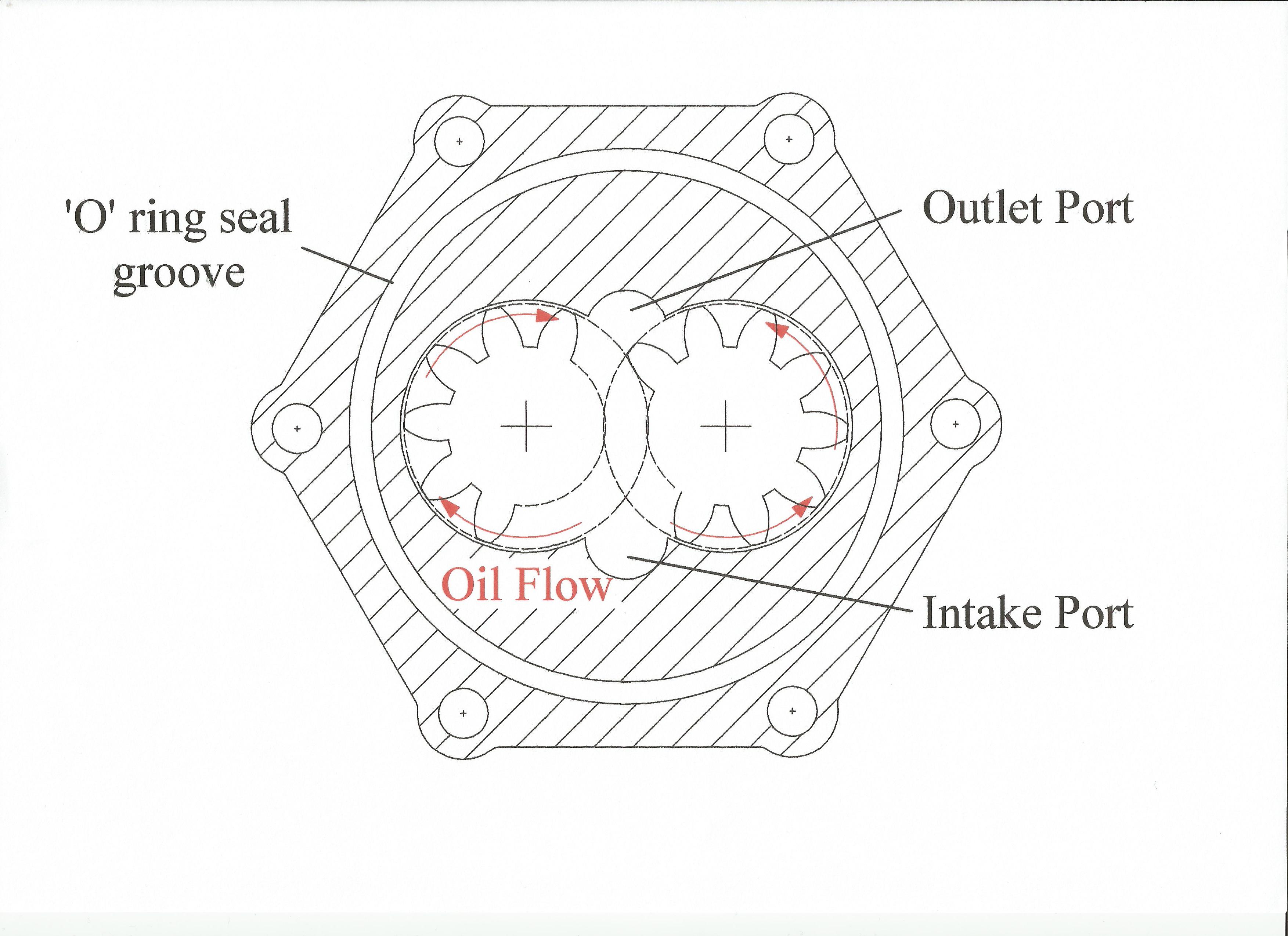 Fig. 1 - Cross-section of the Lucas mechanical fuel pump
Written by John Coxon
5139