Intake manifolds
The design of a modern intake manifold is a relatively straightforward affair. Ensuring that the positive pressure waves reverberating up and down the intake runner arrive just at the same time as the inlet valve is closing sounds simple enough, and given the constraints of a single-cylinder engine at a fixed rotational speed, so it is.
However, add the complexities of a multi-cylinder arrangement at a wide range of engine speeds, feeding through a single throttle plate, and the degree of difficulty begins to increase. Now add a single-point fuelling system – a carburettor – delivering fuel proportional to the pulsating flow of air travelling either in towards the cylinder or out away from it, and you have what was commonly known as a classic race engine, the sort that engine ‘tuners’ at the time would attempt to develop on a day-to-day basis.
A major problem with these engines though would be the distribution of the air-to-fuel ratio across the cylinders. As many of you will know, a gasoline fuel burns the exact amount of air – no more, no less – at an air-to-fuel ratio by mass of around 14.5-14.7:1. This is known as the stoichiometric ratio, and for maximum power it should be increased to nearer 13.0:1. Beyond this the cylinder will run excessively ‘rich’ and the power will fall away. Likewise, running ‘lean’, at 16:1 or greater, and the power falls away but perhaps not as quickly. To generate the maximum performance from a given amount of fuel therefore, each cylinder needs to run at or very near its optimum of 13:1.
Formula regulations in the past could often specify a single carburettor ‘choke’ feeding across all cylinders, and even in some of the best engines the spread of air-to-fuel ratios across the cylinders could be as much as 4:1, so while one cylinder could be running at 11:1, another one next to it could be at 15:1. That may mean an average of 13:1 but the engine is nowhere near delivering its maximum power.
The answer of course lay in the intake manifold, but not just in the distribution of the air – which was never that good anyway – rather mainly in the distribution of the fuel, which was crude to say the least.
In anything other than a straight intake pipe, fuel in the form of droplets will be easily centrifuged out of the airflow as soon as the air meets the first bend in its path. Attaching itself to the outside wall of the bend, the mixture will weaken off momentarily, only to evaporate back into the air stream a short time later. This continual wall wetting and evaporation helped atomisation of the fuel into the air, but at the same time it was difficult to control the amount of fuel eventually travelling down each branch and into the cylinders.
The advent of port fuel injection solved the issue of fuel distribution, leaving the task of air distribution to be solved by other means.
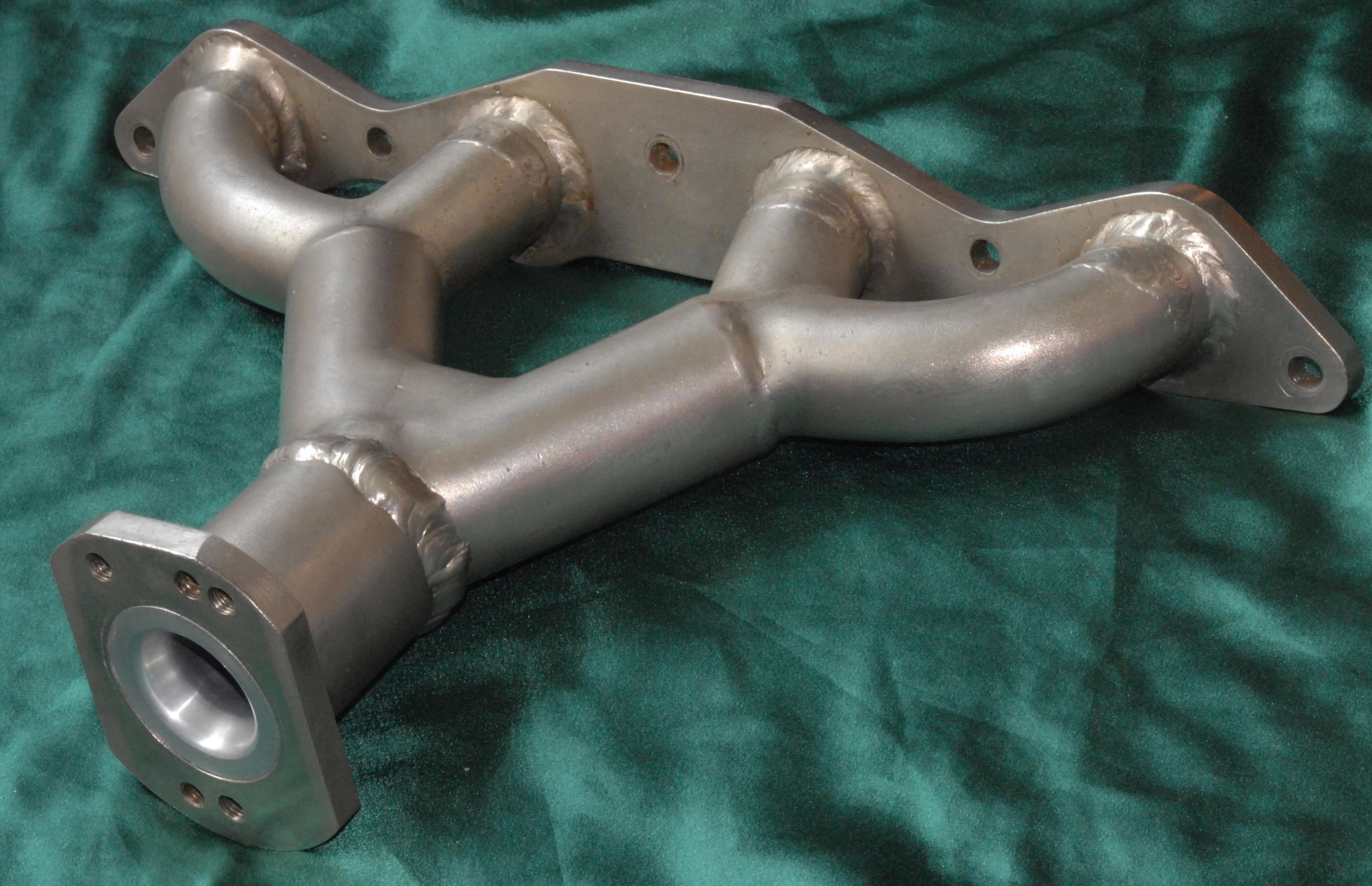
Fig. 1 - Classic intake manifold
Written by John Coxon