Oil coolers
Oil coolers are a vital part of any racecar lubrication system and have to meet a number of exacting design criteria. In many applications, especially where aerodynamic performance is an important part of overall performance, the sizing of coolers can have a big impact on aerodynamic efficiency. The larger the cooler, the larger the inlets required and the greater the drag; the result being that safety margins in the cooling system can be pared back to a minimum.
This means that any coolers used need to be fully optimised, but CFD and wind tunnel resources are an expensive and limited resource so inevitably cooling system testing takes second place to overall aero development. However, there are some specialist facilities that will test for both oil and water cooling systems using purpose-built test rigs and wind tunnels.
For initial evaluations of new cores or cross-correlation studies, simple benchmarking exercises can be conducted quickly and cost-effectively in flat-face templates, onto which the cooler cores are mounted. These are then placed in the test section of a wind tunnel, and the inlet and outlet oil temperatures measured, as well as the air pressure either side of the core. However, where more detailed studies are needed or specific cooling problems have been identified, engineers will look to replicate the on-car installation as closely as possible using the actual car's ducting or even complete sidepods.
The key tools for assessing the cooling efficiency of a core are a number of temperature sensors placed at the inlet and outlet of the core and pitot tubes to measure the inlet and outlet airflow. As temperature-controlled flow air is passed over the outer 'finned' surface of the radiator, a temperature-controlled flow of fluid is passed through the internal tube passages. The system is then run through a predetermined test matrix of differing load and airspeed conditions, with the level of heat dissipation being derived for each condition. More complex air pressure measurements can also be taken using arrays of pitots located behind the cooler core to ascertain pressure distribution across the cooler face and to help identify problems such as stagnant flow areas.
Beyond the basic measurements of inlet and outlet coolant temperatures and airflow velocities at the cooler face, Laser Doppler Anemometry (LDA) - a technique for measuring the direction and speed of fluids, using lasers and 'tracer' particles in the test fluid - and thermal imagery to provide visualisation of core performance can also be used. The use of thermal imaging cameras gives a very clear idea of surface temperatures on the core, allowing for hot and cold spots or blockages to be identified quickly. LDA also allows for detailed analysis of air velocity over the cooler.
In its simplest form, LDA crosses two beams of collimated, monochromatic and coherent laser light through the fluid under test. The beams are normally obtained by splitting a single beam, to ensure that the beams remain coherent. These are then intersected at their focal point, where they interfere with each other, creating a set of straight fringes. The lasers are aligned to be perpendicular to the fluid flow, and as the tracer particles pass through they reflect the light into a photo detector. By measuring the Doppler frequency shift of the light it is then possible to calculate the velocity of the tracer particle and thus the velocity of the fluid.
The end-product of this process produces an image very similar to that created during a CFD simulation, but derived from actual test data. As with the thermal imaging, the process allows for a very rapid assessment of the flow characteristics of a particular installation; changes can then be made and re-assessed to determine the most effective method of installation.
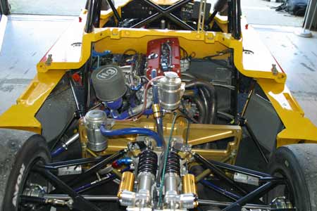
Fig. 1 - Oil cooler requirements need to be accommodated into the overall vehicle aerodynamic package (Photo: Lawrence Butcher)
Written by Lawrence Butcher