Turbo compressor energy efficiency
For the first time, truly, ever in Formula One, 2014 was all about efficiency – in the amount of fuel the 1.6 litre, turbocharged, direct injected engine consumes over a race, and efficiency of the vehicle aerodynamics. And yet, with the amount of fuel used being around 35% less than in 2013, the cars were just about as quick.
Much of the saving, of course, was in the energy recovered under braking, energy that would have otherwise gone to waste in the form of heat out of the exhaust, but in adopting electric motor/generator technology there is so much more potential for efficiency than many might at first think. Take the turbocharger compressor wheel design for instance, and the potential for efficiency savings in compressing the intake charge.
Powered by an exhaust gas-driven turbine or the electric motor of the motor/generator unit, the engine intake air is drawn into the centre of a centrifugal compressor wheel and accelerated radially outwards, increasing the kinetic energy of the intake gas. Having left the perimeter of the wheel, the rapidly moving air is slowed down again, or ‘diffused’, so that the kinetic energy is converted into pressure energy – the intake manifold boost pressure. The design and angle of the blades of the compressor wheel, the diffuser and the scroll of the compressor housing all work together to generate the compression characteristics of the system in the form of a compressor ‘map’, examples of which are shown in Fig. 1.
Essentially a plot of pressure ratio against the mass flow, the left-hand side of the operating envelope is referred to as the ‘surge’ line. At this point the aerodynamic elements of the compressor wheel create reverse flow effects, leading to stress reversals in the compressor blades and a ‘coughing’ type of sound as the airflow stalls. At the other side of the map, towards the right-hand side of the envelope, the limit is one of compression efficiency. Normally taken to be around 60%, at these values excessive heating of the air intake charge takes place, the mass flow drops significantly and the compressor is effectively ‘choked. In between, the map consists of a series of contours connecting points of equal compression efficiency, rather like the height contours on a map, and superimposed on all this are the lines of constant compressor wheel speed.
The operating range, or ‘width’ of the map, is in part a function of the compressor wheel design – the type and the number of blades and their angle of twist. When designed to have a degree of what is called ‘backsweep’, these impeller blades create maps with higher peak compression efficiencies at the expense of being narrower and therefore more difficult to match to engine applications, particularly those used in applications with variable speed and load. In most automotive applications, therefore, the running position of the compressor is governed by the boost pressure which, once achieved, is regulated by the turbine wastegate.
However, if you now throw in the potential to drive the compressor using, say, an electric motor/generator then you now have the opportunity to match the compressor to the peak efficiency point using the electric motor when insufficient exhaust is available or when there is too much gas, to absorb the excess power and feed some of it back into the battery storage system. Either way, the compressor can be redesigned to operate at a more efficient point in its range than would otherwise be the case, producing the minimum heating to the engine intake air and resulting in smaller intercoolers and a more efficient vehicle aerodynamic package.
So not only are the new-for-2014 direct injected engines producing impressive fuel economy, the opportunities available in powering the compressor using an electric motor can make the overall engine vehicle package even more efficient.
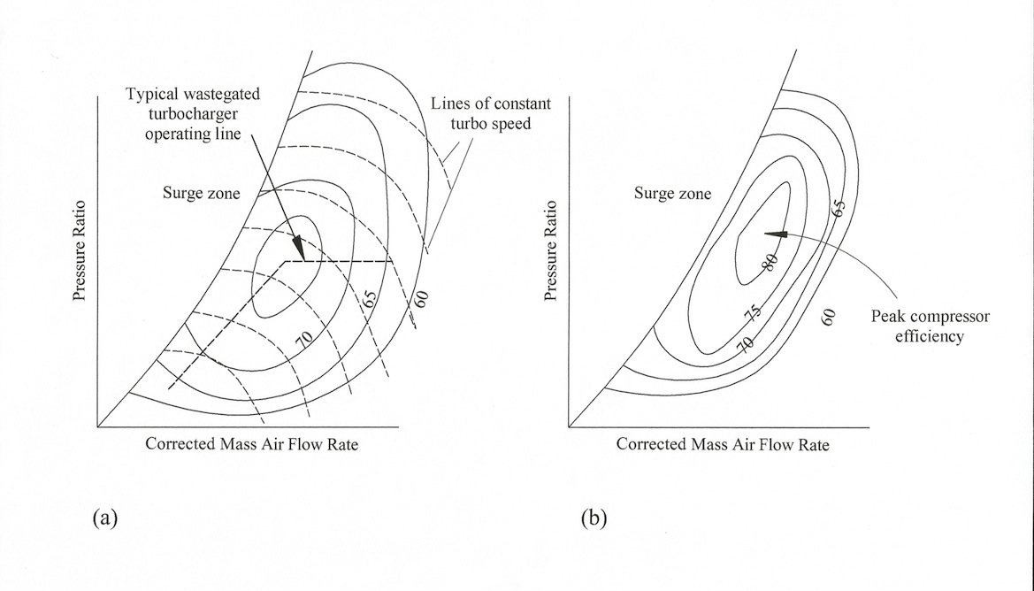 Fig. 1 - Typical turbocharger maps: a) conventional wastegated approach; and b) using an electric motor/generator unit to give higher compression efficiency
Written by John Coxon
6169