Chassis dynamometers - roller size
 As a power unit engineer I must admit I still think in terms of engine dynos. In absorbing the power produced directly off the engine crankshaft - or, perhaps better still, a suitably designed PTO (Power Take Off) - this seems to me the easiest way to map an engine and optimise its performance. But as a pragmatist, I realise there are times when the engine may need to be tested in its environment, and in such cases it is much simpler and quicker to leave it in the vehicle.
Yet while the limitations to the power absorbed by an engine dyno will clearly be determined by examining the dyno specification, the limits to the power absorbed by the chassis dyno is a little less certain. It's all down to the tractive force generated between the tyre and the chassis dyno rollers.
When used to simulate a drive-by cycle, the tractive effort on the chassis dyno is normally small and is expressed as the sum of the frictional forces on the vehicle. These forces are: rolling resistance - caused by bearings, tyres and so on, aerodynamic effects, and those required to accelerate the vehicle, and all have to be programmed into the rollers against vehicle speed, to simulate the loads experienced by the engine.
Now to accurately simulate the forces between the tyre and the ground the roller on which the driven wheels sit has to be as large as possible. This is because when travelling along the road the tyre effectively sees a 'roller' of infinite diameter. However, in trying to absorb the full engine power, as in the case of wide-open throttle performance testing, the tractive effort produced will almost certainly exceed that on a single roller with just the weight of the vehicle to hold it down.
For full-throttle testing, therefore, it would seem much better to use a system of twin rollers when the driven wheel centres itself in the valley between them. With such an arrangement the vehicle can be tied down, usually with flexible straps to give an extra level of security during the test and regain some of the traction area lost.
When twin rollers are used, simple geometry limitations dictate that their diameters need to be much smaller, so the contact patch between the roller and tyre will also be much smaller. However, given that there are now two contact patches - one for each roller - the frictional force may or may not be equivalent to travelling on level ground.
What is certain though is that in trying to increase the maximum tractive force available (by strapping the car down on the rollers even tighter against its springs), energy that would otherwise have been used to power the rollers will have been expended in the increased deflection of the tyres, and therefore the power figures seen on the dyno will not necessarily reflect that produced by the engine. Furthermore, if testing for any length of time then the tyres will invariably overheat, shredding great chunks of rubber around the dyno cell and almost certainly becoming unusable thereafter.
One way around this is to use wheel-driven dynos that bolt directly onto wheel drive flanges. This surmounts the tractive effort issue but, in not deflecting the tyres, reduces the driveline frictional losses and is therefore unrepresentative in a different way.
Chassis dynos, where the drive is taken through the vehicle tyres, certainly have their place but in my opinion for accurate full-throttle work you can't beat an engine dyno.
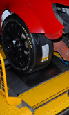
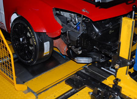
Fig. 1 - Chassis dyno testing
Written by John Coxon