Strain gauging
On many racecars in series such as Formula One and Sportscar racing a large number of sensors, normally strain gauges, are used to assess the loads exerted on individual components within the driveline and suspension. This provides data for calculating the life of parts and later for rig testing and simulation programs. The data generated by these sensors can then be transmitted over a live telemetry link, allowing trackside engineers to monitor components in real time, allowing for the early identification of potential problems and prevention of catastrophic failure. So how do strain gauges operate?
The most common form of strain gauge found in motorsport is an electrical resistor constructed from a foil section bonded to a dielectric backing. When the gauge is stretched or compressed, its electrical resistance varies, and this change can be related to the amount of force on the material. However, the variation is very small, and to measure the strain accurately requires precise measurement of very small changes in resistance. To measure such small changes in resistance, strain gages are almost always used in a bridge configuration with a voltage excitation source. The general configuration is a Wheatstone bridge [Fig. 1] which consists of four resistive arms (the ‘bridges’) with an excitation voltage, VEX, applied across the bridges.
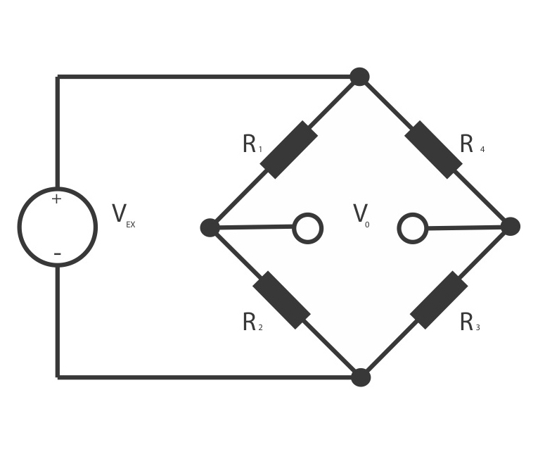
Fig. 1 - schematic layout of a Wheatstone bridge
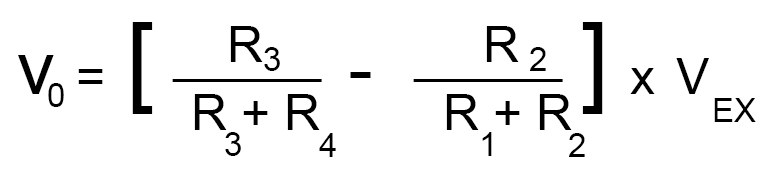
From this schematic, it is apparent that when R1/R2 = R4/R3, the voltage output V0 is zero. Under these conditions, the bridge is said to be balanced, and any change in resistance in any arm of the bridge results in a non-zero output voltage. Therefore, if you replace R4 in Fig. 1 with an active strain gauge, any changes in the gauge’s resistance will unbalance the bridge and produce a non-zero output voltage. It is then possible to create an algorithm in the data acquisition software to convert this output into a unit of force. The basic principle is expressed in the following equation:
This is a very simplified example of the operation of a strain gauge, and careful consideration has to be paid to external factors that can affect the readings obtained. The most significant of these is the effect of temperature on the electrical resistance of the gauge material. Most conductive materials will change electrical resistance as ambient temperature changes, which can lead to false readings.
The solution is to use two strain gauges in each bridge, one of which is a ‘dummy’ gauge placed transversely to the applied strain direction, meaning the strain has little effect on it. The reading from this gauge can then act as a reference for the variation in resistance with temperature, which can then be subtracted from the reading from the gauge fixed along the axis of strain. Both will be affected by temperature in the same way, with the difference between the readings being a measure of the strain. It should be noted though that while this minimises temperature effects it does not completely eliminate them, and other factors also need to be taken into consideration, such as the resistance in any cables running to a signal amplifier and electronic noise from nearby sources.
The advantage of strain gauges is that they can be incorporated into a wide variety of components made from a range of materials, for example integrated into the end of a suspension pushrod as shown in Fig. 2. Often these components are designed to incorporate a strain gauge in their structure, reducing any possible compromise on the part’s intended function. Overall, such components provide engineers with an invaluable insight into the forces components are subjected to when in use.
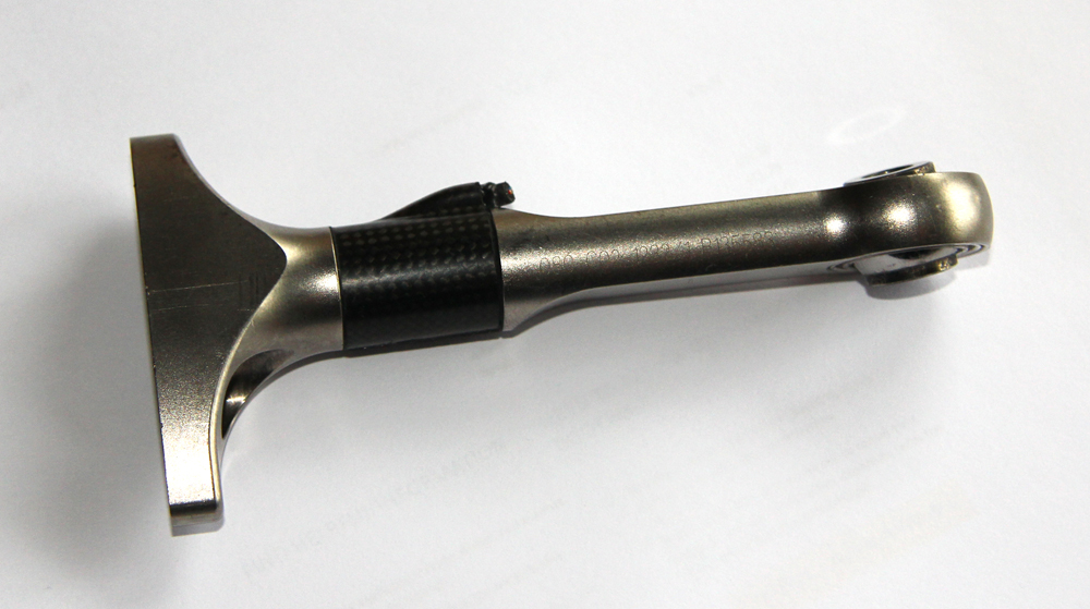
Fig. 2 - A strain gauge incorporated into the end of a Formula One suspension component (Photo: Lawrence Butcher)
Written by Lawrence Butcher