The control freak
 I'm sure we've all been accused of it at some time - the compulsive desire to have things just the way we want them, with little or no compromise. Perfection is the goal, anything else is a poor second best and, except in the case of pure genius perhaps, it is often considered a major flaw in one's character. But in the world of engine dynamometers, control is everything.
Many of you will no doubt be familiar with the large and unmistakable throttle lever alongside the console of an older engine test bed. Linked directly to the engine throttle via an equally unambiguous control cable or metal rod, throttle control was left entirely to the tester, and should anything become amiss or the engine detonate for so much as a split-second, the throttle would be wrenched away from fully open or rammed shut as an instinctive reaction.
With the dyno in 'speed' mode - as opposed to constant torque or power law mode - the engine revs would be restricted and the engine therefore safe from overspeeding. Here, speed control was purely down to the choice of dynamometer. In the case of hydraulic versions, the water pump impeller, situated as it was on the dyno shaft, would pump more water should the engine speed choose to rise, increasing the load. As this load increased, the engine speed would fall and therefore some level of control was inherent in the system. But I seem to remember it wasn't always foolproof.
For the eddy current dyno, things were a little more complicated. Here the magnetic resistance of the rotors, acting as it did on the stator assembly, was governed by the excitation current passing through the field coil.
In its simplest form, control would therefore be obtained from a potentiometer feeding the coil from a DC supply. For a given excitation current the torque absorbed would rise quickly with engine speed and then less rapidly until saturation. At this time the torque absorbed would stay constant.
Inherently some level of slow speed control was obtained but unless the excitation current was increased at higher speeds, control would be lost. When speed stabilisation was necessary at higher speeds, this excitation current would be used to modify the torque/speed characteristic and an electronic method used.
With modern dynamometer systems, almost regardless of design, control is relegated to the software, in particular the presence of the Proportional, Integral and Derivative (PID) loop. Here, speed control (or indeed any form of parameter control, be it temperature, load or whatever) is obtained by taking the error signal - the difference between the Set Point and the Measured Point - and adjusting the output of the controller to reduce it. Closed-loop PID routines can therefore be found everywhere in modern digital control systems.
In the case of an engine speed control system, the Proportional part adjusts the signal instantaneously in proportion to the change in engine rpm. For instance, if the error is reduced by half, then this element of control will act to reduce the next error computed by the same factor. This component controls the bulk of the response but, as readers will probably realise, the set value can never properly be achieved since the error is only halved after each loop.
Sometimes referred to as the 'gain' in the system for the Measured Point and the Set Point to coincide there are two other correction factors.
One of these is the Integral component. This serves to reduce the error over the longer term. So long as the error is never zero this element will continue to increase. When the instantaneous error is zero it has little effect, but if the set point is overshot, the error value changes its polarity and a negative term added to the integral. The term 'drift correction' might be a better description here.
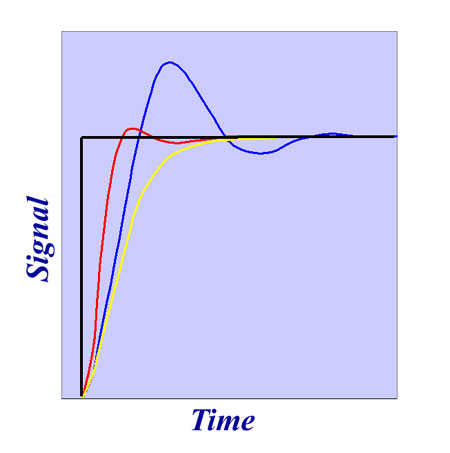
The third component, the Derivative, has a damping effect on the system but also improves its response time. Linked to the rate of change of the error, this component is therefore larger when sudden changes occur. It is highest during the initial transient change and has the effect of 'flattening' the response curve, reducing the tendency to overshoot.
So the next time you are called a control freak, take it as a sign of genius and consider it a compliment! But remember the terms - Proportional, Integral and Derivative.
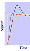
Fig. 1 - Variations in control in response to a digital input
Written by John Coxon