Water brake dynos
 Water brake dynamometers are some of the most popular devices for engine bench testing, thanks to their relative simplicity and low cost. They are also ideally suited to the testing of high-output engines, thanks to the scalability of their design.
Water brakes use water flow proportional to the applied load to create resistance to the test engine's output. A controlled flow of water through the inlet manifold is directed at the centre of the rotor in each absorption section; the water is then expelled towards the outside of the dynamometer body by centrifugal force. As it is directed outwards, the water is accelerated into pockets on the stationary stator plates, where it is decelerated. This continuous acceleration/deceleration of the water creates the applied load to the motor. Through this transfer of energy, the water is heated and discharged.
However, water brakes are generally used only for steady-state measurements, as opposed to dynamic testing, because of the non-linear torque characteristics of the water brake system and the problems this creates in terms of regulating load control. Water brakes can also be prone to instability as a result of high-frequency pressure pulses created by the movement of the water, which causes problems such as excessive vibration and results in torque and load oscillations.
One method of controlling or limiting the effect of these pulsations is through improved rotor design. Advances in CFD (computational fluid dynamics) over the past decade have allowed for far more accurate modelling of the fluid behaviour inside the dynamometer. This in turn allows manufacturers to refine the design of the rotor and stator components to reduce the occurrence of the high-frequency pulses, or ensure that they occur outside the dyno's normal operating window. The main benefit of these refinements is that they allow water brakes to run at higher revs while still retaining accuracy and repeatability.
Beyond simply refining the design of the internal components, other approaches have also been used to improve the stability of water brakes. One notable method was pioneered by General Electric, to address stability problems encountered when testing very high output motors. The solution uses the injection of high-pressure air into the brake housing, which has the effect of raising the partial pressure within the brake, preventing or dampening any high-frequency pulses. The volume of air injected varies depending on the load applied to the dyno, with the volume being determined based on a mathematical model specific to the type and size of water brake.
While this approach no doubt improves the performance of the water brake system, it also brings a considerable increase in complexity, not only in the construction of the brake itself but also the control systems, with a separate microcontroller needed to service the air injection system.
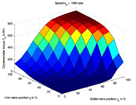
The same developments in CFD that have aided improvements in stability are also increasing the potential uses of water brakes in a dynamic role. By being able to accurately model the torque characteristics of the brake, which are dictated by the positions of the inlet and outlet water valves, the non-linearity of the torque curve can be accounted for. This data can be used as a reference map that is then used by a feedback controller to accurately govern the torque of the water brake as an engine is run dynamically. Note though that other factors such as inlet and outlet water temperatures also need to be accounted for, as these have a considerable effect on the torque characteristics.
These developments are in their early stages, but they go to show that although the water brake may be relatively old technology, it still has potential as a versatile engine test bed.
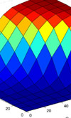
Fig. 1 - Map showing water brake torque in relation to inlet and outlet water valve position (From "Inverse Torque Control of Hydrodynamic Dynamometers for Combustion Engine Test Benches", by TE Passenbrunner, M Trogmann and L del Re, American Control Conference 2011)
Written by Lawrence Butcher