Combined valve locks and lash caps
Some engine components are generally ‘out of the limelight’ as far as coverage in motorsport publications are concerned. Race Engine Technology magazine and these RET-Monitor articles tend to cover most items in detail, so you can find articles covering the most minor of components. Valve locks (collets, or cotters if you prefer) and lash caps (valve shims) are among those we cover, and are among the smallest and lightest parts in a race engine.
Like me, you may be surprised to learn that some companies have combined the function of these components, the merits of this being lower cost, improved reliability, lower mass and reduced complexity. The component resulting from this unusual marriage, known as a lash lock, is actually, as is the case with any conventional valve lock, a pair of components that allow the locks to engage with a groove cut into the valve stem.
Where the lash cap and valve locks are separate components, the lash cap contacts the top of the valve stem, but in the case of lash locks, this is not always the case. In order to locate properly in the stem groove, the lash cap part of the component must remain clear of the valve in all cases. Allowance therefore needs to be made for the case where the groove is in its most distant position relative to the end of the stem. The load transfer is then not via the top of the valve stem but through the wall of the lash lock.
The result of having a split component is that the top surface of the lash lock is not continuous and flat – there is a cut that crosses it. Thankfully, on the components I have seen pictures of, the cut is not a simple straight line but is in an ‘S’ shape, meaning that the end of any rocker will not come to an abrupt ‘valley’ as it traverses the top of the lash lock. Such a straight cut might have an upsetting influence on valvetrain dynamics if the rocker tip were to ‘drop’, however slightly, into the groove and have to climb out again. If we rely on having a nominally flat top to a conventional lash cap for reasons of lubrication – to sustain an oil film in sliding or rolling motion – the gap in the lash lock’s top surface will adversely affect this.
If these lash locks were used in overhead camshaft (OHC) engines with inverted bucket followers, this would not be a concern. The lash cap, where it is used to change the valve clearances, is a very simple component to change for one of the correct thickness, and certainly for OHC engines this is the way valve clearances are adjusted. However, for a lash lock, the act of changing the component is far more complex, as we have to compress the valve spring as we would when installing or removing the valve locks.
It remains to be seen whether such components take an increasing share of the market from conventional valve locks and lash caps, but at the moment they seem to be a niche offering.
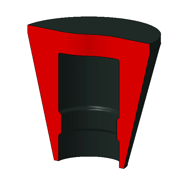
Fig. 1 - A CAD model of a combined lash cap and valve lock
Written by Wayne Ward
5550