Welded rods, an advantage?
 In previous articles about pushrods, several designs have been discussed and explained. And although in these articles the developments, manufacturing and control processes are said to have matured over the years, there are still many race series worldwide where top-end pushrods are not used.
Often the reason is product cost. These race series rely on performance parts that are not as sophisticated as the high-level series, or not even production components. That's not to say these components are any worse, but what could be the downside of using them in your valued race engine?
In this article I want to focus on friction-welded pushrods, specifically on the welding process. As stated in my earlier RET-Monitor article, pushrod ends are typically pressed into the pushrod tube to achieve the function of the pushrod, actuation of the valve train.
When using a pushrod with pressed-in rod ends, the press fit can become loose, allowing the rod ends to hammer the tube when the engine is running and risking engine damage, potentially ruining the engine. To make sure this can't happen, it is common practice to weld the rod ends to the tube after press-fit of the rod ends. Both laser and friction welding can be used. The welding itself is a critical process, as the cup is a hardened, high carbon-content component that is not ideal for welding.
An alternative manufacturing process could be to reverse the welding and heat treatment processes, which means hardening the rod ends after welding. The drawbacks with this though are that the rod-end hardness will be lower than with loose rod ends and that it requires a significant investment and increase in product cost. Based on the assumption that we are looking for a cost-effective alternative, the overall volume of high-performance pushrods does not allow for these kinds of investment levels.
Friction welding is mostly chosen when the priority is product cost. Compared to laser welding, however, it is not as easy to control, and in order to ensure sufficient quality of the weld, proper process control is essential at the end of the manufacturing process.
A typical test procedure consists of applying a rotating bending load onto the rod ends. This allows the total welded areas to be loaded and maximises the chances of the more severe internal defects being found.
A comparison of this test procedure can be made with the functional loads on the pushrod, where a radial force acts on the rod ends due to the layout of the valvetrain systems and the arch-shaped movement of the rocker. What needs to be taken into account, however, is the fact that the test loading required can be physically applied to the rod ends.
The rod itself needs to be held firmly in position at the moment the test load is applied. Tube material has lower mechanical properties and therefore is not as strong, so there's the risk of the tube being damaged or even deformed during the rotational bending test. On the other hand, when the loads are reduced so as not to damage the tube, one might doubt the representativeness of the test procedure.
This test procedure is called non-destructive. That means the part will not - or, as mentioned, should not - be damaged during the test and can therefore be sold to the customer.
Also, in order to be able to determine the correct test boundary conditions such as test load, load direction, rotational speed, amount of revolutions in the test, test duration and so on, the load at which the part will actually fail needs to be known. To gain enough information and experience, a destructive test may be needed. The goal of a destructive test is always to find out the circumstances in which a part fails, after which the results can be compared to the initial design guidelines and assumptions.
So, given that the focus here is on the friction weld rather than the rest of the pushrod, we should ask ourselves which test will provide sufficient information about the weld itself. To investigate the welded zone, a tensile test can be performed. This will provide a good insight into the strength of the welded zone and which area is most critical.
For example the detailed shape from tube to rod end, including wall thickness and the original press-fit area, can be analysed. If the rod is designed and welded properly, the heat-influenced zone will suffer from an initial crack under tensile stress in the pushrod, just before another area starts to fail. If the welding process is not yet as stable as required, welding defects will result in preliminary failure of the part. As long as this component does not find its way into a high-performance race engine, this can be seen as an advantage and possibly improve the product and process.
My goal here has been to focus on the processes following the pushrod's design phase, and not limited to the manufacturing process. Quality control is also just as important in order to ensure that only quality parts leave the supplier. The example of the friction welding process should make engineers aware of the fact that knowing the loads and testing them are two different things. And since the race engineering industry consists not only of high level professional race teams but many race enthusiasts as well - who often use standard automotive products - I hope quality will not be taken for granted.
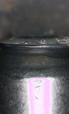
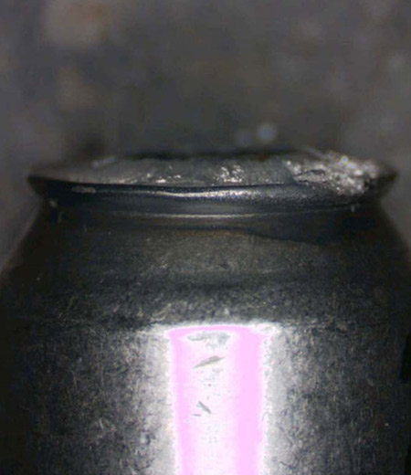
Fig. 1 - Pushrod breakage after tensile quality testing
Written by Dieter van der Put
5358